
Intel Xeon Processor and Intel E7500/E7501Chipset Compatible Platform Design Guide

Intel
®
Xeon™ Processor and Intel
®
E7500/E7501 Chipset Compatible Platform Design Guide 109
Hub Interface
7.3 Hub Interface 1.5 Implementation
The Hub Interface 1.5 signals HI[7:0] are associated with HI_STBS/HI_STBF. For those familiar
with Hub Interface 1.0, HI_STBF and HI_STBS are called HI_STB# and HI_STB, respectively.
This section documents the routing guidelines for the Hub Interface 1.5 that is responsible for
connecting the MCH to the ICH3-S. Hub Interface 1.5 supports parallel termination mode only;
therefore, the DPRSLPVR pin on the ICH3-S must be left as No Connect (NC); this signal has an
internal pull-down.
7.3.1 Hub Interface 1.5 High-Speed Routing Guidelines
The Hub Interface signals must be routed directly from the MCH to ICH3-S with all signals
referenced to ground. Maintain a consistent ground reference plane at all times. In addition, route
all signals within a data group (consisting of nine bits of data and a pair of strobes) on the same
layer and reference them to the same ground plane. Keep layer transitions to a minimum. If a layer
change is required, use only two vias per net and keep all signals within a data group on the same
layer.
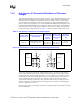
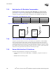
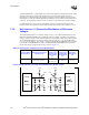
The Hub Interface 1.5 signal groups are listed in Table 7-6. The general routing guidelines for the
Hub Interface 1.5 signals are given in Table 7-7.
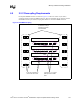
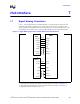
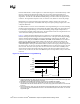
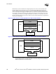
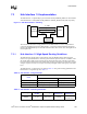
Figure 7-7. 8-Bit Hub Interface 1.5 Routing
Intel
®
ICH3-S
CLK
Synthesizer
CLK66 CLK66
HI[11:0]
HI_STBS
HI_STBF
MCH
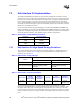
Table 7-6. Hub Interface 1.5 Signal Groups
Group
Signals
MCH Intel
®
ICH3-S
Common Clock Signals HI_A[11:8] HI[11:8]
Source Synchronous Signals HI_A[7:0], HI_STBF, HI_STBS HI[7:0], HI_STBF, HI_STBS
Miscellaneous Signals HIRCOMP_A, HISWNG_A, HIVREF_A HICOMP, HITERM, HIREF
Table 7-7. Hub Interface 1.5 Routing Parameters
System Type
Trace Length
Min-Max
Trace Z
0
Trace
Width/Spacing
Breakout
Width/Spacing
266 MHz 3” – 20” 50 Ω ± 10% 5/15 mils
5/5 mils
(max dist = 0.5”)