
Dual Intel Xeon Processor Voltage Regulator Down (VRD) Design Guidelines

Dual Intel
®
Xeon™ Processor Voltage Regulator Down (VRD) Guidelines
6
Intel®
Xeon™
Processor
Voltage Regulator
Down Simplified
Model
S1
Equivalent model
L
VR
R
VR
R
CABLE*
L
CABLE*
psu
R
CABLE*
L
CABLE*
R
MB1
*
L
MB1
*
R
MB1
*
L
MB1
*
C
BULK
L
BULK
R
BULK
S2
Board Model
Power Supply
ESL
INPUT
ESR
INPUT
C
INPUT
Intel Xeon
Processor
Equivalent model
L
HF2
R
HF2
C
HF2
L
HF1
R
HF1
C
HF1
L
HF2
R
HF2
C
HF2
R
MB2
L
MB2
R
MB2
L
MB2
R
MB2
L
MB2
R
MB2
L
MB2
Remote sense
connection points
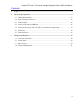
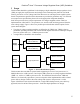
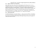
Figure 2 – Base VRD Electrical Delivery Model
Table 1 lists model parameters for the motherboard. These values are guidelines, which will vary
according to board layout and component selection. The ultimate VRD and power distribution
requirement is to meet the die-level Vcc specifications in the processor data sheet or EMTS.
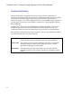
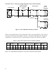
Table 1– Intel
®
Xeon™ Processor Power Delivery Models
Supply
Motherboard
Capacitance
Capacitor Inductance Capacitor Resistance Motherboard
Inductance
Motherboard
Resistance
C
BULK
(µF)
C
HF1
(µF)
C
HF2
(µF)
L
BULK
(pH)
L
HF1
(pH)
L
HF2
(pH)
R
BULK
(mΩ)
R
HF1
(mΩ)
R
HF2
(mΩ)
L
MB1
(pH)
L
MB2
(pH)
R
MB1
(mΩ)
R
MB2
(mΩ)
V
CC
10008 352 264 172 68 90 0.667 1.25 0.833 12.7 60 0.03 0.29
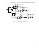
Figure 3 is a simplified block diagram of a four-phase, interleaved VRD example.