
Voltage Regulator Module (VRM) and Enterprise Voltage Regulator-Down (EVRD) 10.1 Design Guidelines

Voltage Regulator Module (VRM) and Enterprise Voltage 7
Regulator-Down (EVRD) 10.1 Design Guidelines
1 Applications
1.1 Introduction and Terminology
This document defines DC-to-DC converters to help meet the power requirements of computer
systems using Intel
®
Xeon™ processor with 800 MHz system bus and 64-bit Intel® Xeon™
processor MP. Some SKUs of the Intel
®
Xeon™ processor with 800 MHz system bus only require
the power requirements of VRM/EVRD 10.0, although all SKUs are capable of operating under
VRM/EVRD 10.1 envelope. Refer to the Intel
®
Xeon™ Processor with 800 MHz System Bus
Datasheet for more details. SKUs of the 64-bit Intel
®
Xeon™ processor MP with 4MB L3 cache at
2.8GHz, 64-bit Intel
®
Xeon™ processor MP with 8MB L3 cache at 3.0GHz and 64-bit Intel
®
Xeon™ processor MP with 8MB L3 cache at 3.33 GHz require an additional VRM 9.1 regulator
for cache power. SKUs of the 64-bit Intel
®
Xeon™ processor MP with 1MB L2 cache require a
common core and cache voltage rail. In addition, some SKUs of the Intel
®
Xeon™ processor MP
are capable of operating under the VRM 10.2L envelope. Requirements will vary according to the
needs of different computer systems and processors that a specific voltage regulator is expected to
support.
The intent of this document is to define electrical, thermal and mechanical specifications for
VRM 10.1.
VRM – The voltage regulator module (VRM) designation in this document refers to a voltage
regulator that is plugged into a baseboard, where the baseboard is designed to support more than
one processor. VRM output requirements in this document are intended to match the needs of a set
of microprocessors.
EVRD – The Enterprise Voltage Regulator-Down (EVRD) designation in this document refers to a
voltage regulator that is embedded on a baseboard. The EVRD output requirements in this
document are intended to match the needs of a set of microprocessors. Each implementation of a
specific board must meet the specifications of all processors supported by the board.
‘1’ – In this document refers to a high voltage level (V
OH
and V
IH
).
‘0’ – In this document refers to a low voltage level (V
OL
and V
IL
)
‘#’ – Symbol after a signal name in this document refers to an active low signal, indicating that a
signal is in the asserted state when driven to a low level.
The specifications in the processor’s datasheet always take precedence over the data provided in
this document.
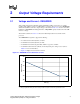
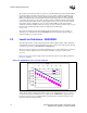
VRM/EVRD 10.1 incorporates functional changes from prior EVRD and VRM guidelines:
• Continuous load core current (Icc
TDC
) (thermal design current) has been increased to 105A
(Section 2.1).
• A maximum core current (Icc
MAX
) has been increased to 120 A.
• Maximum current slew rate has been increased to 930 A/µs.
• Vcc load line limits have been changed and control pins have been added to select multiple
load line impedances.
§