
Intel Xeon Processor with 800 MHz System Bus Thermal/Mechanical Design Guide

Intel® Xeon™ Processor with 800 MHz System Bus Thermal/Mechanical Design Guidelines 39
Mechanical Drawings A
The mechanical drawings included in this appendix. These drawings refer to the thermal
mechanical enabling components for the Intel Xeon Processor with 800 MHz System Bus.
Note: Intel reserves the right to make changes and modifications to the design as necessary.
Table A-1. Mechanical Drawing List
Drawing Description Figure Number
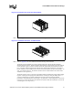
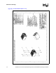
2U CEK Heatsink (Sheet 1 of 4) Figure A-1
2U CEK Heatsink (Sheet 2 of 4) Figure A-2
2U CEK Heatsink (Sheet 3 of 4) Figure A-3
2U CEK Heatsink (Sheet 4 of 4) Figure A-4
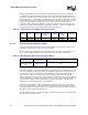
CEK Hat Spring (Sheet 1 of 3) Figure A-5
CEK Hat Spring (Sheet 2 of 3) Figure A-6
CEK Hat Spring (Sheet 3 of 3) Figure A-7
Baseboard Keepout Footprint Definition and Height Restrictions for Enabling
Components (Sheet 1 of 6)
Figure A-8
Baseboard Keepout Footprint Definition and Height Restrictions for Enabling
Components (Sheet 2 of 6)
Figure A-9
Baseboard Keepout Footprint Definition and Height Restrictions for Enabling
Components (Sheet 3 of 6)
Figure A-10
Baseboard Keepout Footprint Definition and Height Restrictions for Enabling
Components (Sheet 4 of 6)
Figure A-11
Baseboard Keepout Footprint Definition and Height Restrictions for Enabling
Components (Sheet 5 of 6)
Figure A-12
Baseboard Keepout Footprint Definition and Height Restrictions for Enabling
Components (Sheet 6 of 6)
Figure A-13
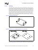
1U CEK Heatsink (Sheet 1 of 4) Figure A-14
1U CEK Heatsink (Sheet 2 of 4) Figure A-15
1U CEK Heatsink (Sheet 3 of 4) Figure A-16
1U CEK Heatsink (Sheet 4 of 4) Figure A-17
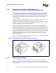
4-pin Fan Cable Connector (for active CEK Heatsink) Figure A-18
4-pin Baseboard Fan Header (for active CEK Heatsink) Figure A-19