
Intel Xeon Processor with 800 MHz System Bus Thermal/Mechanical Design Guide

Intel® Xeon™ Processor with 800 MHz System Bus Thermal/Mechanical Design Guidelines 33
Thermal/Mechanical Reference Design
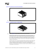
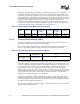
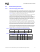
2.4.7.3 Hat Spring
The hat spring, which is attached on the secondary side of the baseboard, is made from 0.80 mm
[0.0315 in.] thick 301 stainless steel half hard. Any future versions of the spring will be made from
a similar material. The hat spring has four embosses (called “hats”) which, when assembled, rest
on the top of the chassis standoffs. The hat spring is located between the chassis standoffs and the
heatsink standoffs. The purpose of the hat spring is to provide compressive preload at the TIM
interface when the baseboard is pushed down upon it. This spring does not function as a clip of any
kind. The two tabs on the spring are used to provide the necessary compressive preload for the
TIM when the whole solution is assembled. The tabs make contact on the secondary side of the
baseboard. In order to avoid damage to the contact locations on the baseboard, the tabs will be
insulated with a 0.127 mm [0.005 in.] thick Kapton* tape (or equivalent). Figure 2-12 shows an
isometric view of the hat spring design.
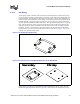
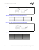
Please refer to Appendix A for more detailed mechanical drawings of the hat spring. Also, the
baseboard keepout requirements shown in Appendix A must be met to use this hat spring design.
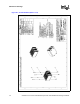
Figure 2-12. Hat Spring Isometric View
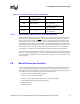
Figure 2-13. Isometric View of Hat Spring Attachment to the Base Board
Primary
Secondary
Secondary Primary