
Intel Xeon Processor Multiprocessor Platform Design Guide


89
Processor Power Distribution Guidelines
In addition, high-frequency decoupling may be required for signal integrity. System boards
designed using striplines with V
CC_CPU
and V
SS
references should not require high-frequency
decoupling beyond that recommended above. For systems using microstrip configurations a return
path discontinuity will exist between the processor and the baseboard due to the baseboard traces
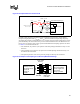
having only one reference plane. These systems should distribute decoupling capacitors as shown
in Table 8-1 and described as follows:
• Four minimum, six preferred 1 µF capacitors with 0805 packages distributed evenly over the
data lines.
• Three minimum, four preferred 1 µF capacitors with 0805 packages distributed evenly over
the address and control lines.
• All capacitors placed as close to the processor package as the keep-out zone allows.
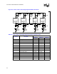
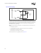
Figure 8-18. Implementation 2 No Discrete R
VCC
VCCA
VSSA
VCCIOPLL
L1/L2
L1/L2
C
C
Processor
PLL
R-Socket
603
R-Trace
R-Socket
603
R-Socket
603
R-Trace
Processor interposer "pin"
Baseboard v ia that connects
f ilter to VCC plane
Trace < 0.02 Ω
Socket 603 pin
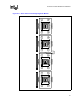
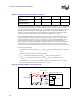
Figure 8-19. Example of Decoupling for a Microstrip Baseboard Design
Address and
Cntrl Pins
Data Pins
4-6 0.1[ uF ] with
603 body over the
data signals and as
close to the CPU
package as
possible
4-6 0.1[ uF ] with
603 body over the
data signals and as
close to the
package as
possible
3-4 0.1[ uF ] with 603
body over the address
and cntrl
signals and
as close to the chipset
package as possible
3-4 0.1[ uF ] with 603
body over the address
and cntrl signals and
as close to the
package as possible
Cavity under
Processor