
Intel Xeon Processor Multiprocessor Platform Design Guide


58
Mechanical and EMI Design Considerations
Differential clocking can also reduce the amount of noise coupled to other traces, which improves
signal quality and reduces EMI. I/O signals are particularly important because they often leave the
system chassis (serial and parallel ports, keyboards, mouse, etc.) and will radiate noise that has
been induced onto them. A single-ended clock's return path is usually a reference plane, which is
shared by other signals/traces. When noise is created on a single-ended clock, the noise will appear
on the reference plane and may be coupled to I/O traces. A differential clock's return path is the
clock-bar signal/trace, which is more isolated than the reference plane and minimizes potential I/O
trace coupling.
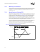
For best results, the trace lengths and routing of the clock lines must be closely matched and
spacing between the two traces should be kept as small as possible. This will minimize loop area
and maximize H-field cancellation. In addition, the real and parasitic terminations of each signal of
a differential pair should be the same. Also, the skew between the signal level transitions on the
two lines must be small compared to the rise time of the level transitions.
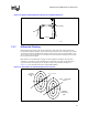
Placing ground traces on the outside of the differential pair may further reduce emissions.
Intermediate vias to ground may be needed to reduce the opportunity for re-radiation from the
ground traces themselves. Distance between vias should be less than ¼ of a wavelength of the fifth
harmonic of the processor core frequency.
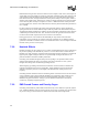
7.2.8 Heatsink Effects
Heatsink grounding may be an effective way to reduce system EMI emissions. Noise coupled from
the processor package to the heatsink may cause it to act as an antenna and re-radiate the noise.
Heatsink size, shape, fin pattern, orientation and material may all impact its ability to reradiate the
high-frequency signals. Designers will have to experimentally investigate the behavior of a
particular heatsink to determine its EMC performance.
Grounding of the heatsink through the Intel processor package is not possible with the current
package implementation but may be an option at some time in the future. As such, system
designers must design their own heatsink grounding solution.
When designing a grounding mechanism for the heatsink, care must be taken to minimize the
impedance and distance between the ground paths. Typical guidelines suggest ground points
should be separated by less than ¼ wavelength of the third harmonic of the processor core
frequency.
Grounding materials should be selected to eliminate galvanic action between the various metals in
contact. Oxidation of the various materials should also be considered as some oxides are non-
conductive (for example, aluminum oxide) and will degrade EMC performance over time.
Manufacturing process residue or coatings to prevent oxidation should also be checked for
conductivity, especially at high frequencies.
7.2.9 EMI Ground Frames and Faraday Cages
Grounding of heatsinks may reduce EMI, but that alone may not be sufficient to pass the required
tests. Additional shielding of the processor itself may be necessary. A Faraday cage placed around
the processor may provide a reduction in radiated noise and make chassis design easier.