
Intel Xeon Processor Multiprocessor Platform Design Guide


44
System Bus Routing
6.4.2.1 Topology 1: Asynchronous GTL+ Signals Driven by the Processors;
FERR#, IERR#, PROCHOT# and THERMTRIP#
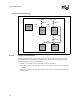
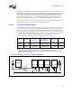
These signals should adhere to the following routing and layout recommendations. Figure 6-9
illustrates the recommended topology. When routing to middle agents connect in true daisy chain
topology. Do not create a stub to connect to the socket pins. Note that FERR# is the only signal in
this group that connects between the processor(s) and the chipset. PROCHOT#, THERMTRIP#
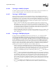
and IERR# are connected to other motherboard logic and may need voltage translation logic
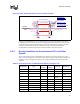
depending on voltage input thresholds of the motherboard receiver logic devices used. Figure 6-10
shows an example voltage translator circuit.
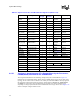
Signal Name Type
Processor
I/O Type
Topology
Number
Driven by Received by
ODTEN Other I 7
Pull-Up /
Pull-Down
Processor
PROCHOT# Asynchronous GTL+ O 1 Processor External Logic
PWRGOOD Asynchronous GTL+ I 2 External Logic Processor
RESET#
SKTOCC# Other O 9 Processor External Logic
SLP# Asynchronous GTL+ I 2 Chipset Processor
SM_ALERT#
1
SMBus Interface O 4 SMBus Agent
SMBus agent/
Processor
SM_CLK
1
SMBus Interface I/O 4 SMBus Agent Processor
SM_DAT
1
SMBus Interface I/O 4 SMBus Agent Processor
SM_EP_A[2:0]
1
SMBus Interface I 4
Pull-Up /
Pull-Down
Processor
SM_TS_A[1:0]
1
SMBus Interface I 4
Pull-Up /
Pull-Down
Processor
SM_WP
1
SMBus Interface I 4
Pull-Up /
Pull-Down
Processor
SMI# Asynchronous GTL+ I 2 Chipset Processor
STPCLK# Asynchronous GTL+ I 2 Chipset Processor
TAP signals TAP See Section 6.4.3
TESTHI[6:0] Other I 8 Pull-Up Processor
THERMTRIP# Asynchronous GTL+ O 1 Processor External Logic
V
CCA
Power I See Section 8.13
V
CCIOPLL
Power I See Section 8.13
V
CCSENSE
Other O See Section 8.13
VID[4:0] Other O 3 Processor VRM
V
SSA
Power I See Section 8.13
V
SSSENSE
Other O See Section 8.13
GTLREF Power I See Section 8.12.1
Table 6-4. Asynchronous GTL+ and Miscellaneous Signal List (Sheet 2 of 2)