
Intel Xeon Processor and Intel E7500/E7501Chipset Compatible Platform Design Guide


Intel
®
Xeon™ Processor and Intel
®
E7500/E7501 Chipset Compatible Platform Design Guide 217
High-Speed Design Concerns
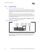
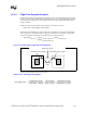
12.5.4 DDR Example
The DDR Source Synchronous bus requires groups of 8 signals and 2 strobes to be length tuned
within 25 mils. Given that the PCB trace length for DDRA_DQS2 is 3.85 inches, what is the
solution space for DDRA_DQS11 and DDRA_DQ20?
To determine the PCB solution space for the signal DDRA_DQ20, you need the PCB length of the
strobe DDRA_DQS11. So, we will find the length for DDRA_DQS11 first. Using Equation 12-2 as
a basis:
DDRA_DQS11
PCB_length
= ( (DDRA_DQS2
MCH_length
/ DDRA_DQS2
MCH_velocity
)
+ (DDRA_DQS2
PCB_length
/ DDRA_DQS2
PCB_velocity
)
– (DDRA_DQS11
MCH_length
/ DDRA_DQS11
MCH_velocity
) )
* DDRA_DQS11
PCB_velocity
± Tolerance
We can find the MCH package velocities and trace lengths in the
Intel
®
E7501 Chipset Memory
Controller Hub (MCH) Datasheet
, “Chipset Interface Trace Length Compensation” Chapter. The
datasheet states that the trace delay due to signal velocity is the inverse of velocity. The MCH
package trace delay due to signal velocity is 150 ps/in, so the velocity is (150 ps/in)
-1
. The PCB
trace delay due to signal velocity is 175 ps/in, so the velocity is (175 ps/in)
-1
. The MCH package
trace length for DDRA_DQS2 is 356.06 mils, DDRA_DQS11 is 567.48 mils, and DDRA_DQ20 is
690.51 mils.
DDRA_DQS11
PCB_length
= ( (0.35606 in * 150 ps/in)
+ (3.850 in * 175 ps/in)
– (0.56748 in * 150 ps/in) )
/ 175 ps/in ± 0.025 in
= 3.669 in ± 0.025 in
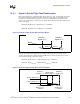
By setting the PCB length of DDRA_DQS11 as close to 3.669 in as possible, we can have a wider
solution space for all 8 of the signals which need to be length tuned to DDRA_DQS2 and
DDRA_DQS11. Next, let’s find the PCB length for DDRA_DQ20. Using Equation 12-2 as a basis:
DDRA_DQ20
PCB_length
= ( (DDRA_DQS2
MCH_length
* DDRA_DQS2
MCH_velocity
)
+ (DDRA_DQS2
PCB_length
* DDRA_DQS2
PCB_velocity
)
– (DDRA_DQS20
MCH_length
* DDRA_DQS20
MCH_velocity
) )
* DDRA_DQ20
PCB_velocity
± Tolerance
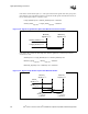
Then, using the values from above and simplifying the velocity yields:
DDRA_DQS11
PCB_length
= ( (0.35606 in * 150 ps/in)
+ (3.850 in * 175 ps/in)
– (0.69051 in * 150 ps/in) )
/ 175 ps/in ± 0.025 in
= 3.563 in ± 0.025 in