
Intel Xeon Processor and Intel E7500/E7501Chipset Compatible Platform Design Guide


High-Speed Design Concerns
212 Intel
®
Xeon™ Processor and Intel
®
E7500/E7501 Chipset Compatible Platform Design Guide
12.5 Length Tuning
Note: This section does not apply to the Processor System Bus.
High speed source synchronous interfaces have very small setup and hold window.s As a result, the
signals as a group are very sensitive to skew. A common way to reduce skew is to tune all of the
lengths such that the setup and hold windows have the same positional relationship. Length tuning
is the matching of two or more signals’ total flight time, within a tolerance, to center the setup and
hold windows.
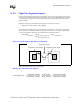
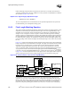
Length tuning has several key parameters: signal to be tuned, absolute minimum flight time,
absolute maximum flight time, and tolerance. The absolute minimum and maximum flight times
define the flexible solution space which lengths may fall within. For a signal to be properly tuned,
it must fall within that solution space and be within the length tuning tolerance. Figure 12-7 shows
the relationship of these parameters.
A tolerance is a value specifying how far off from exact is allowed. Typically, tolerance is specified
in a specific direction, such as –1 ps or ± 2 ps. In the first instance, the total tolerance window or
solution space is 1 ps; the second the solution space is 4 ps.
The minimum and maximum allowed flight times are at the end points of the tolerance window.
The tolerance window may fall anywhere within the range between absolute minimum flight time
and maximum flight time. The remainder of this section will simply refer to “minimum allowed
flight time” as “minimum flight time” and will refer to “maximum allowed flight time” as
“maximum flight time.”
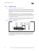
Figure 12-7. Length Tuning Parameters
absolute
minimum
flight time
absolute
maximum
flight time
tolerance
Signal flight time
Signals
minimum
allowed
flight time
maximum
allowed
flight time