
64-bit Intel Xeon Processorwith 1MB L2 Cache Thermal/Mechanical Design Guidelines
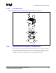
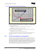
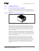
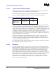
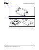
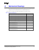
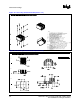
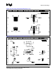
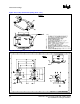
Table Of Contents
R
64-bit Intel
®
Xeon™ Processor MP with 1 MB L2 Cache 27
Thermal/Mechanical Design Guidelines
A Mechanical Drawings
The mechanical drawings included in this appendix. These drawings refer to the thermal mechanical
enabling components for the 64-bit Intel Xeon processor MP with 1 MB L2 cache.
Note: Intel reserves the right to make changes and modifications to the design as necessary.
Table A-1. Mechanical Drawing List
Drawing Description Figure Number
2U Cooling Solution Heatsink (Sheet 1 of 4) Figure A-1
2U Cooling Solution Heatsink (Sheet 2 of 4) Figure A-2
2U Cooling Solution Heatsink (Sheet 3 of 4) Figure A-3
2U Cooling Solution Heatsink (Sheet 4 of 4) Figure A-4
Cooling Solution Hat Spring (Sheet 1 of 3) Figure A-5
Cooling Solution Hat Spring (Sheet 2 of 3) Figure A-6
Cooling Solution Hat Spring (Sheet 3 of 3) Figure A-7
Baseboard Keepout Footprint Definition and Height Restrictions for
Enabling Components (Sheet 1 of 5)
Figure A-8
Baseboard Keepout Footprint Definition and Height Restrictions for
Enabling Components (Sheet 2 of 5)
Figure A-9
Baseboard Keepout Footprint Definition and Height Restrictions for
Enabling Components (Sheet 3 of 5)
Figure A-10
Baseboard Keepout Footprint Definition and Height Restrictions for
Enabling Components (Sheet 4 of 5)
Figure A-11
Baseboard Keepout Footprint Definition and Height Restrictions for
Enabling Components (Sheet 5 of 5)
Figure A-12