
64-bit Intel Xeon Processor with 2MB L2 Cache Thermal/Mechanical Design Guidelines

Thermal/Mechanical Reference Design
36 64-bit Intel® Xeon™ Processor with 2MB L2 Cache Thermal/Mechanical Design Guidelines
The fan outputs a SENSE signal, an open-collector output, which pulses at a rate of two pulses per
fan revolution. A baseboard pull-up resistor provides V
CC
to match the baseboard-mounted fan
speed monitor requirements, if applicable. Use of the SENSE signal is optional. If the SENSE
signal is not used, pin 3 of the connector should be tied to GND.
It is recommended that a 4 pin fan header be used on the baseboard, in addition to, a control ASIC
that can send a PWM signal to the active fan heatsink solution on the 4
th
pin, at a nominal 25 KHz
frequency. If a 3-pin CPU fan header is used instead, the active fan heatsink solution will revert
back to an automatic ambient air temperature control mode.
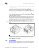
The fan power header on the baseboard must be positioned to allow the fan heatsink power cable to
reach it. The fan power header identification and location must be documented in the supplier’s
platform documentation, or on the baseboard itself. The baseboard fan power header should be
positioned within 177.8 mm [7 in.] from the center of the processor socket.
Note: System board should pull this pin up to V
CC
with a resistor.
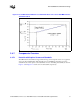
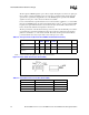
Table 2-6. Fan Specifications (Boxed 4-wire PWM/T-diode Heatsink Solution)
Description Min
Typ
Steady
Max
Steady
Max
Startup
Unit Notes
+12V: 12 Volt Fan Power
Supply
10.8 12 12 13.2 V
IC: Fan Current Draw N/A 1.5 1.25 1.5 A
SENSE: SENSE
Frequency
2 2 2 2 Pulses per fan revolution Note
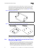
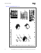
Figure 2-18. Fan Cable Connection (Active CEK)
Table 2-7. Fan Cable Connector Pin Out (Active CEK)
Pin Number Signal Color
1 Ground (Constant) Black
2 Power (+12V) Yellow
3 Signal: 2 pulses per revolution Green
4 Control Blue