
Intel Xeon Processor with 800 MHz System Bus Thermal/Mechanical Design Guide


Intel® Xeon™ Processor with 800 MHz System Bus Thermal/Mechanical Design Guidelines 61
Test Setup Methodology
Note: The processor and TTV are extremely fragile components. To avoid damage, it is very important
that special attention be given when milling a channel into the IHS.
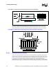
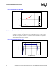
For illustration, the measurement location for a 42.5 mm x 42.5 mm [1.673 in. x 1.673 in.] flip-
chip micro pin grid array 4 (FC-mPGA4) package with 31 mm x 31 mm [1.22 in. x 1.22 in.] IHS is
shown in Figure B-21. In case of conflict, the package dimensions in the Intel® Xeon™ Processor
with 800 MHz System Bus at 2.80 GHz and 3.60 GHz Datasheet supersede dimensions provided in
this document.
NOTE: Measure from edge of processor.
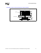
B.1.2.2 Processor Local Air Thermocouple Placement
For passive heatsinks, two thermocouples will be placed 10 mm upstream of the processor
heatsink. The thermocouples will be centered with respect to the height of the heatsink fins and
evenly across the width of the heatsink as shown in Figure B-22.
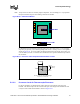
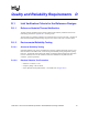
Figure B-20. 0° Attachment Method
Figure B-21. 0° Processor Case Temperature Measurement Location
21.25 mm
[0.837 in].
42.5 mm x 42.5 mm FC-mPGA Package
31.0 mm x 31.0 mm IHS
21.25 mm
[0.837 in]