
Intel Xeon Processor and Intel E7500/E7501Chipset Compatible Platform Design Guide

Hub Interface
108 Intel
®
Xeon™ Processor and Intel
®
E7500/E7501 Chipset Compatible Platform Design Guide
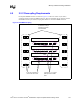
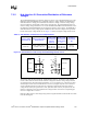
7.2.3 Hub Interface 2.0 Resistive Compensation
The hub interface uses a resistive compensation signal (HIRCOMP_x) to compensate buffer
characteristics across temperature, voltage, and process. The HIRCOMP_x resistor values are
given in Table 7-5. Figure 7-6 shows the RCOMP_x circuits. The length of the trace from the
component to the pull-up must be less than 1 inch and have a trace impedance of 50 Ω ± 10%.
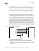
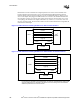
7.2.4 Hub Interface 2.0 Decoupling Guidelines
To improve I/O power delivery, use two, 0.1 µF capacitors per component (i.e., MCH, P64H2).
These capacitors should be placed within 150 mils of each package, adjacent to the rows that
contain the hub interface. If the layout allows, wide metal fingers running on the VSS side of the
board should connect the VCC1_8/VCC1_2 side of the capacitors to the VCC1_8/VCC1_2 power
pins. Similarly, if layout allows, metal fingers running on the VCC1_8/VCC1_2 side of the board
should connect the ground side of the capacitors to the VSS power pins.
7.2.5 Unused Hub Interface 2.0 Interfaces
Terminate unused Hub Interface 2.0 interfaces as described below:
• All hub interface data and strobe, HIRCOMP_x, and HISWNG_x signals can be left as no
connects.
• HIVREF must be tied low to ground.
Table 7-5. Hub Interface 2.0 RCOMP Resistor Values
Component Trace Impedance RCOMP Resistor Value RCOMP Resistor Tied To
MCH 50 Ω ± 10% R1 = 24.9 Ω ± 1% VCC1_2
Intel
®
P64H2 50 Ω ± 10% R2 = 61.9 Ω ± 1% VCC1_8
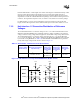
Figure 7-6. Hub Interface 2.0 RCOMP Circuits
HIRCOMP_x
R1
1.8 V
Intel
®
P64H2
HI_RCOMP
R2
1.2 V
< 1.0" < 1.0"
MCH