
603 Pin Socket Design Guidelines

603 Pin Socket Design Guidelines
R
11
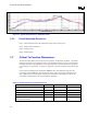
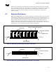
3.3.3.2. Lock (closed) and Unlock (open) Markings
For lock an unlock positions on the socket they are to be marked with the universal symbol of the locked
and unlocked pictures. Clear indicator marks must be located on the actuation mechanism that identifies
the lock (closed) and unlock (open) positions of the cover as well as the actuation direction. These
marks should still be visible after a package is inserted into the socket.
Lock (closed) Unlock (open)
3.3.3.3. Lot Traceability:
Each socket will be marked with a part number and lot identification code that will allow traceability of
all components, date of manufacture (year and week), and assembly location. This mark can be an ink
mark or a laser mark but must be able to withstand a temperature of 240°C for 40sec (minimum) per
Section 3.6.2 and must pass the solvent resistance test in Section 5.3. The mark must be placed on a
surface that is visible when mounted on a printed circuit board. In addition, this identification code
must be marked on the exterior of the box in which the units ship.
3.3.3.4. Socket Size:
The socket size must meet the dimensions as shown in Figure 9-4 (Appendix A.4)and Figure 9-5
(Appendix A.5), allowing full insertion of the pins in the socket, without interference between the
socket and the pin field. The processor (not the pin shoulder) must sit flush on the socket. The 603 Pin
Socket and actuation area must fit within the keep-in zone defined in Figure 9-5 (Appendix A.5).
3.3.3.5. Socket/Processor pin field Movement:
The socket shall be built so that the processor pin field displacement will not exceed 1.52mm (in the y-
direction, i.e. North-South) during engagement and disengagement.
3.3.3.6. Orientation in Packaging and Shipping and Handling:
Packaging media needs to support high volume manufacturing.
3.3.4. Contact Characteristics:
3.3.4.1. Number of Contacts:
Total number of contacts: 603.
3.3.4.2. Base Material:
High strength copper alloy.