
Voltage Regulator Module (VRM) and Enterprise Voltage Regulator-Down (EVRD) 10.2 Design Guidelines

Voltage Regulator Module (VRM) and Enterprise Voltage 15
Regulator-Down (EVRD) 10.2 Design Guidelines
Output Voltage Requirements
The processor load may not be sufficient to absorb all of the energy from the output capacitors on
the baseboard, when VID changes to a lower output voltage. The VRM/EVRD design should
ensure that any energy transfer from the capacitors does not impair the operation of the
VRM/EVRD, the AC-DC supply, or any other parts of the system.
2.7 Overshoot at Turn-On or Turn-Off - REQUIRED
The core VRM/EVRD output voltage should remain within the load-line regulation band for the
VID setting, while the VRM/EVRD is turning on or turning off, with no over or undershoot out of
regulation. No negative voltage below –100 mV may be present at the VRM/EVRD output during
turn-on or turn-off.
2.8 Output Filter Capacitance - REQUIRED
The output filter capacitance for the VRM/EVRD based designs will be located on the baseboard.
The system design must ensure that the output voltage of the VRM/EVRD conforms to the load
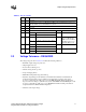
line of Figure 2-2 and with the baseboard and processor loads. Table 2-2 shows the number of
decoupling caps recommended and other related specifications based on updated processor power
requirements supported by VRM/EVRD 10.2.
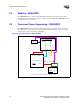
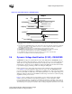
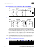
Figure 2-7 and Figure 2-8 are the recommended examples of a baseboard decoupling solution and
a processor load. The number of capacitors needed could change based on updated processor
power requirements. The values shown are for a four-phase 200 kHz to 800 kHz switching voltage
regulator design. The parasitic board values are extracted from a design using four layers of the
board with 2 ounces total of copper for Vcc and 2 ounces total of copper for ground. The type and
number of bulk decoupling required is dependent on the voltage regulator design and it is highly
recommended that the OEM work with the VRM supplier for an optimal decoupling solution for
their system and in accordance to the processor’s design requirements.
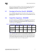
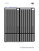
Table 2-2. Recommended Decoupling and Other Specifications for Supported Processors
Processor
560 µF Alum-
Polymer
10 µF MLCC
Slew Rate
(di/dt)
A/µs
Thermal
Design
Current (A)
Max Icc (A)
64-bit Intel® Xeon™
processor MP with up
to 8MB L3 cache
12 44 770 86 91
64-bit Intel® Xeon™
processor MP with
1MB L2 cache
14 45 575 105 120