
Intel Xeon Processor with 800 MHz System Bus Thermal/Mechanical Design Guide

78 Intel® Xeon™ Processor with 800 MHz System Bus Thermal/Mechanical Design Guidelines
Processor Thermal Management Logic and Thermal Monitor Features
System integrators that plan on using the thermal diode for system or component level fan control
need to be aware of the potential for rapid changes in processor power consumption as the
executing workload changes. Variable performance thermal solutions that fail to react quickly to
changing workloads may experience TCC activation or worse yet, result in automatic shutdown via
THERMTRIP# (refer to Appendix F.1.7.2 for more information on THERMTRIP). One example
of this situation is as follows: A fan control scheme slows the fans such that the processor is
operating very near the thermal trip point while executing a relatively low power workload. The
start of a higher power application creates a sudden increase in power consumption and elevates
the temperature of the processor above the trip point, causing the TCC to activate. The power
reduction resulting from TCC activation slows the rate of temperature increase, but is not sufficient
to clamp the temperature, due to inadequate thermal solution performance at reduced fan speed. As
a result, the temperature continues to slowly increase. The fan is then sped up to compensate for the
change in processor workload but reacts too slowly to prevent the processor from shutting down
due to THERMTRIP# activation.
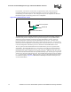
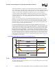
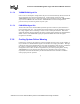
High temperature change rates on-die can also limit the ability to accurately measure the on-die
thermal diode temperature. As a result, the on-die thermal diode should not be relied upon to warn
of processor cooling system failure or predict the onset of the TCC. An illustration of this is as
follows. Many thermal diode sensors report temperatures a maximum of 8 times per second.
Within the 1/8
th
(0.125 sec.) second time period, the temperature is averaged over 1/16
th
of a
second. In a scenario where the silicon temperature ramps at 50°C/sec, or approximately 6°C/
0.125 sec, the processor will be ~4.5°C above the temperature reported by the thermal sensor.
Change in diode temperature averaged over 1/16
th
seconds = ~1.5°C; temperature reported 1/16
th
second later at 1/8
th
second when the actual processor temperature would be 6°C higher (see
Figure F-30).
The on-die thermal diode can be used with an external device (thermal diode sensor) to monitor
long-term temperature trends. By averaging this data information over long time periods (hours/
days vs. min/sec), it may be possible to derive a trend of the processor temperature. Analysis of
this information could be useful in detecting changes in the system environment that may require
attention. Design characteristics and usage models of the thermal diode sensors are described in
datasheets available from the thermal diode sensor manufacturers.
Figure F-30. On-Die Thermal Diode Sensor Time Delay
Processor Temperature
Time in 1/16
th
Second Intervals
Temperature is Averaged over
1/16
th
Second
Temperature is
Reported 1/16
th
Second Later
Processor
Temperature Ramp