
Intel Xeon Processor and Intel E7500/E7501Chipset Compatible Platform Design Guide

Intel
®
Xeon™ Processor and Intel
®
E7500/E7501 Chipset Compatible Platform Design Guide 75
System Bus Routing Guidelines
A system intending to support both packaged versions of the processor needs to include a method
for selecting which method (SMBus versus direct diode) from which to obtain thermal data and
properly interface with all signals listed in Table 5-9. The following sections describe a hardware
and firmware method for supporting both package types.
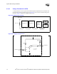
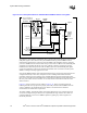
5.5.2.1 Hardware Selection of SMBus Thermal Devices
Figure 5-10 illustrates a hardware method for selecting the correct thermal sensor device when
either an Intel Xeon processor with 512-KB L2 cache or Intel Xeon processor with 533 MHz
system bus is installed. This reference circuit needs to be applied to both processor sockets.
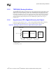
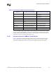
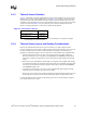
Table 5-9. Functionality for SMBus and Thermal Diode Pins
Signal (Pin)
Intel
®
Xeon™ Processor with
512-KB L2 Cache (INT-mPGA)
Intel
®
Xeon™ Processor with
533 MHz System Bus (FC-mPGA2)
THERMDA1 (Pin Y27) N/C: Not used by processor
Output: Provides access to anode of
thermal diode.
THERMDC1 (Pin Y28) N/C: Not used by processor
Output: Provides access to cathode of
thermal diode.
SM_CLK (Pin AC28) Input: SMBus clock N/C: Not used by processor
SM_DAT (Pin AC29) I/O: SMBus data signal N/C: Not used by processor
SM_ALERT# (Pin AD28)
Output: Asserted by thermal sensor
device
N/C: Not used by processor
SM_TS1_A[1:0] (Pin AA28,
Y29)
Input: Thermal Sensor Select Address N/C: Not used by processor
SM_EP_A[2:0] (Pin AB28,
AB29, AA29)
Input: EEPROM Select Address N/C: Not used by process
SMB_PRT (Pin AE4) Reserved: Hi-Z Output: Grounded on package
SM_WP (Pin AD29) Input: EEPROM Write Protect N/C: Not used by process