
Intel Xeon Processor and Intel E7500/E7501Chipset Compatible Platform Design Guide


Schematic Checklist
238 Intel
®
Xeon™ Processor and Intel
®
E7500/E7501 Chipset Compatible Platform Design Guide
13.4 Intel
®
82870P2 P64H2 Schematic Checklist
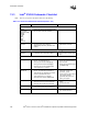
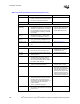
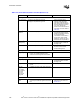
Table 13-4. Intel
®
P64H2 Schematic Checklist (Sheet 1 of 4)
Checklist Items Recommendations Comments
Hub Interface
HI_[21,20,18:0]
PUSTRBF
PUSTRBS
PSTRBF
PSTRBS
• Connect to the MCH. • Refer to Section 7.2.1
HI_[19] • HI[19] must be left as no connect.
HI_RCOMP • 61.9
Ω ± 1% pull-up to 1.8 V. • Refer to Section 7.2.3
HI_VREF
HI_VSWING
• P64H2 Hub reference swing voltage
= 0.800 V ± 5%.
• P64H2 Hub reference voltage = 0.350 V ± 5%.
• R4 = 261
Ω ± 1%, R5 = 332 Ω ± 1%,
R6 = 750
Ω ± 1%.
• Decouple the P64H2 pin with a 0.01 µF.
• Decouple the network nodes with a 0.1 µF
• Refer to Section 7.2.2
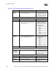
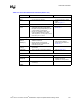
PCI/PCI-X Bus Interface
PxAD[63:32]
PxC/BE[7:4]#
PxDEVSEL#
PxFRAME#
PxIRDY#
PxTRDY#
PxSTOP#
PxPERR#
PxSERR#
PxREQ[5:0]#
PxGNT[5:4,2:0]#
PxPLOCK#
PxPAR64
PxACK64#
PxREQ64#
•8.2 k
Ω ± 5% pull-up to 3.3 V.
• Pull-ups on PxAD[63:32], PxC/BE[7:4]#,
PxPAR64 not needed if bus only contains
64-bit devices
• See the
PCI Specification,
Revision 2.2
.
PAGNT3# • 8.2 k
Ω ± 5% pull-down to ground.
PBGNT3# • 8.2 k
Ω ± 5% pull-down to ground.
IDSEL • The series resistor to the device IDSEL should
be 100
Ω.
NOTE: The P64H2 does not have an IDSEL pin.
Instead, the designer can chose a pin from
PxAD[31:17].
• This has changed from the
PCI-X 1.0 Specification. There
is a specification change that
allows for values other than the
original 2 k
Ω value.
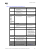
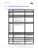
3.3Vaux • Leave this as unconnected on the PCI slots. • The P64H2 does not support
PCI bus power management.
PxPCIXCAP • 8.2 k
Ω ± 5% pull-up to 3.3 V. • See PCI-X Specification
recommendations for
PxPCIXCAP connection.
Px_133EN • For 133 MHz (max) PCI-X capable bus:
8.2 k
Ω ± 5% pull-up to 3.3 V.
• For 100 MHz (max) PCI-X capable bus:
8.2 k
Ω ± 5% pull-down to ground.
• Only active if Px_PCIXCAP pins
are high.