
Intel Xeon Processor and Intel E7500/E7501Chipset Compatible Platform Design Guide


Intel
®
Xeon™ Processor and Intel
®
E7500/E7501 Chipset Compatible Platform Design Guide 233
Schematic Checklist
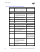
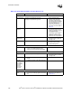
Hub Interface
HI[11:0]
HI_STBS
HI_STBF
• No pull-up resistor required. • Refer to Section 7.3.1.
HICOMP • 78.7
Ω ± 1% pull-up to 1.8 V. • Refer to Section 7.3.3.
HIREF
HITERM
• HREF = 0.350 V +
5%.
• HITERM = 0.700 V ± 5%.
• R4 = 261
Ω ± 1%, R5 = 825 Ω ±1%.
• Decouple the ICH3-S pin with a 0.01 µF.
• Decouple the network nodes with a 0.1 µF
• Refer to Section 7.3.2.
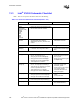
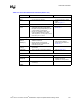
IDE Checklist
PDD[15:0]
SDD[15:0]
• No extra series termination resistors or
other pull-ups/pull-downs are required.
• PDD7/SDD7 does not require a 10 k
Ω pull-
down resistor.
• Refer to ATA ATAPI-6
specification.These signals
have integrated series resistors.
• Refer to Section 9.1.3.
NOTE: Simulation data indicates
that the integrated series
termination resistors are a nominal
33
Ω, but can range from 31 Ω to
43
Ω.
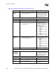
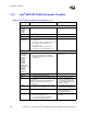
PDIOW#
PDIOR#
PDDACK#
PDA[2:0]
PDCS1#
PDCS3#
SDIOW#
SDIOR#
SDDACK#
SDA[2:0]
SDCS1#
SDCS3#
• No extra series termination resistors. Pads
for series resistors can be implemented
should the system designer have signal
integrity concerns.
• These signals have integrated
series resistors.
• Refer to Section 9.1.3.
•
NOTE: Simulation data
indicates that the integrated
series termination resistors are
a nominal 33
Ω, but can range
from 31
Ω to 43 Ω.
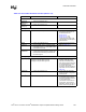
PDREQ
SDREQ
• No extra series termination resistors.
• No pull-down resistors required.
• These signals have integrated
series resistors in the ICH3-S.
• These signals have integrated
pull-down resistors in the
ICH3-S.
• Refer to Section 9.1.3.
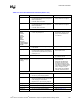
PIORDY
SIORDY
• No extra series termination resistors.
•4.7 ± 5% k
Ω pull-up to 3.3 V
• These signals have integrated
series resistors in the ICH3-S.
• Refer to Section 9.1.3.
IRQ14
IRQ15
• 8.2 k
Ω – 10 kΩ pull-up to 3.3 V
• No extra series termination resistors.
• Open drain outputs from drive.
• Refer to Section 9.1.3.
IDERST# • The PCIRST# signal should be buffered to
form the IDERST# signal. A 22 – 47
Ω
series resistor is recommended on this
signal.
• Refer to Section 9.1.3.
Table 13-3. Intel
®
ICH3-S Schematic Checklist (Sheet 2 of 6)
Checklist Items Recommendations Comments