
Voltage Regulator Module (VRM) and Enterprise Voltage Regulator-Down (EVRD) 10.2 Design Guidelines


Voltage Regulator Module (VRM) and Enterprise Voltage 29
Regulator-Down (EVRD) 10.2 Design Guidelines
7 VRM – Mechanical Guidelines
7.1 VRM Connector - EXPECTED
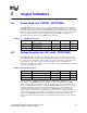
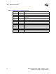
The part number and vendor name for the connector can be found in Table 7-1. The VRM interface
with the system board is a 27-pin pair edge connector. The connector uses latches to hold the VRM
in place. The connector will be rated to handle a continuous load current of 130 A.
NOTE:
1. These vendors are listed by Intel as a convenience to Intel's general customer base, but Intel does not make
any representations or warranties whatsoever regarding quality, reliability, functionality, or compatibility of
these devices. This list and/or these devices may be subject to change without notice.
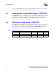
7.2 VRM Connector Keying
7.2.1 Connector Keying
• Single notch between pins 3 and 4 (51 and 52 opposite side).
• Single notch between pins 12 and 13 (42 and 43 opposite side).
• Single notch between pins 21 and 22 (33 and 34 opposite side).
7.2.2 Connector Pin 1 Orientation
Referencing Figure 7-1, Outline Drawing, Far Side (FS) pins sequence 1 through 27, left to right.
Near Side (NS) pins sequence 54 through 28. Pin 1 and 54 are opposite one another.
7.3 Pin Descriptions and Assignments
Table 7-2 shows the VRM 10.2 connector pin description. Pin assignments are shown in Table 7-3.
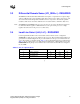
Table 7-1. VRM 10.2 Connector Part Number and Vendor Name
Connector Vendor Part Number Note
Tyco / Elcon 283-0172-01303B (Molded) 1
283-0172-00900B (Machined)
284-0202-03003 (Surface mount)