
Voltage Regulator Module (VRM) and Enterprise Voltage Regulator-Down (EVRD) 10.0 Design Guidelines

VRM and EVRD 10.0 Design Guidelines
R
17
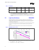
to the processor socket as the keepout zones allow. If backside passive components are allowed in
the design, it would be beneficial to place the 32 capacitors under the processor socket on the
backside of the baseboard. Five of the 560 µF capacitors should be placed on one side of the
processor socket and five on the other side as close to the processor socket as the keepout zones
allow.
Note: The amount of bulk decoupling needed is dependent on the voltage regulator design. Some
multiphase buck regulators may have a higher switching frequency that would require a different
output decoupling solution to meet the processor load line requirements than that described in
this document.
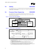
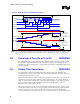
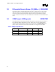
The impedance values labeled “Socket and Package Pins” are supplied by Intel Corporation and
are beyond the control of the system designer. They represent the mPGA604 socket and the
processor package.
For VRM applications, it is recommended that the system designer work with the VRM supplier
to ensure proper implementation of the VRM converter.
Figure 9. Model of Processor Load
Socket and
Package Pins
0.34m
20 pH
PWL
80 µF5600 µF
VR
1.25 m
150 pH
0.7 m
400 pH
8 X 10 µF
1206
10 X 560 µF
Al-Poly
0.3m
10 pH
320 µF
0.32 m
38 pH
32 X 10 µF
1206
Baseboard
VR
Sense
Point
Table 2. Capacitor Recommendations
Qty Value Tolerance Temp Coeff ESR (mΩ) ESL (nH) Notes
10 560 µF Al-Polymer ±20% N/A 7 4.0
8 10 µF Ceramic ±20% X6S 10 1.2 1
32 10 µF Ceramic ±20% X5R or X6S 10 1.2
NOTES:
1. This row corresponds to the capacitors in the processor socket cavity.
2.10 Shut-Down Response REQUIRED
Once the VRM/EVRD is operating after power-up, if either the Output Enable signal is
deasserted or
VID[5:0] = X11111, the VRM/EVRD should turn off its output (the output should
go to high
impedance) within 500 ms.