
Voltage Regulator Module (VRM) 10.2L Design Guidelines


Output Indicators
26 Voltage Regulator Module (VRM) 10.2L Design Guidelines
It is recommended that hysteresis be designed into the thermal sense circuit to prevent a scenario in
which the VR_hot# signal is rapidly being asserted and de-asserted.
6.3 Load Indicator Output (Load Current) - PROPOSED
The VRM may have an output with a voltage (Load Current) level that varies linearly with the
VRM output current. The PWM controller supplier may specify a voltage-current relationship
consistent with the controller’s current sensing method. Baseboard designers may route this output
to a test point for system validation.
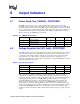
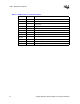
6.4 VRM Present (VRM_pres#) - EXPECTED
The VRM should have the VRM_pres# signal. This signal is an output signal used to indicate to the
system that a VRM is plugged into the socket. VRM_pres# is an open-collector/drain or equivalent
signal. Table 6-3 shows the VRM_pres# pin specification. It is EXPECTED that the pull-up
resistor will be located on the baseboard and will not be integrated into the VRM.
§
Table 6-3. VRM_pres# Specifications
Symbol Parameter Min Max Units
I
OL
Output Low Current 0 4 mA
V
OH
Output High Voltage 0.8 5.5 V
V
OL
Output Low Voltage 0 0.4 V