
Intel Xeon Processor with 800 MHz System Bus Thermal/Mechanical Design Guide

Intel® Xeon™ Processor with 800 MHz System Bus Thermal/Mechanical Design Guidelines 27
Thermal/Mechanical Reference Design
heatsink needs to be 0.06 cm. [0.024 in] longer for a 0.231 cm [0.093 in] thick board, compared to
a 0.157 cm [0.062 in] thick board. .If this solution is intended to be used on baseboards that fall
outside of this range, then some aspects of the design, including but not limited to the hat spring
design and the standoff heights, may need to change. Therefore, system designers need to evaluate
the thermal performance and mechanical behavior of the CEK design on baseboards with different
thicknesses.
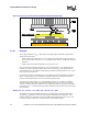
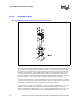
Refer to Appendix A for drawings of the heatsinks and hat spring. The screws and standoffs are
standard components that are made captive to the heatsink for ease of handling and assembly.
Electronic versions of mechanical and thermal models of the CEK are available on http://
www.developer.intel.com.
Note: Intel reserves the right to make changes and modifications to the design as necessary.
Note: The thermal mechanical reference design Appendix D for the Intel Xeon Processor with 800 MHz
System Bus was verified according to the Intel validation criteria given in Appendix D. Any
thermal mechanical design using some of the reference components in combination with any other
thermal mechanical solution needs to be fully validated according to the customer criteria. Also, if
customer thermal mechanical validation criteria differ from the Intel criteria, the reference solution
should be validated against the customer criteria.
2.4.4.3 Structural Considerations of CEK
As Intel explores methods of keeping thermal solutions within the air-cooling space, the mass of
the thermal solutions is increasing significantly. Due to the flexible nature (and associated large
deformation) of baseboard-only attachments, Intel reference solutions, such as CEK, are now
commonly using direct chassis attach (DCA) as the mechanical retention design. The mass of the
new thermal solutions is large enough to require consideration for structural support and stiffening
on the chassis.
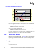
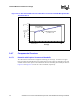
2.4.5 Thermal Solution Performance Characteristics
The optimization of the CEK heatsinks for thermal performance has been completed. Figure 2-10
and Figure 2-11 show the performance of the 2U+ and 1U passive heatsinks, respectively. These
figures show the thermal performance and the pressure drop through fins of the heatsink versus the
airflow provided. The best-fit equations for these curves are also provided to make it easier for
users to determine the desired value without any error associated with reading the graph.