
Intel Xeon Processor with 800 MHz System Bus Thermal/Mechanical Design Guide

20 Intel® Xeon™ Processor with 800 MHz System Bus Thermal/Mechanical Design Guidelines
Thermal/Mechanical Reference Design
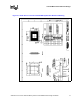
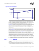
Profile and hence the long-term reliability requirements. For this purpose, Intel has defined a new
parameter, called T
CONTROL
as explained in Chapter 2.2.2, to be used in FSC designs to ensure
that the long-term reliability of the processor is met while keeping the system level acoustic noise
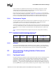
down. Figure 2-5 depicts the relationship between T
CONTROL
and FSC methodology.
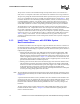
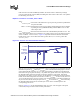
Once the T
CONTROL
value is determined as explained earlier, the thermal diode temperature
reading from the processor can be compared to this T
CONTROL
value. A fan speed control scheme
can be implemented as described inTable 2-7 without compromising the long-term reliability of the
processor.
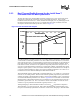
There are many different ways of implementing fan speed control, including FSC based on
processor ambient temperature, FSC based on processor thermal diode temperature (T
DIODE
) or a
combination of the two. If FSC is based only on the processor ambient temperature, low acoustic
targets can be achieved under low ambient temperature conditions. However, the acoustics cannot
be optimized based on the behavior of the processor temperature. If FSC is based only on the
thermal diode, sustained temperatures above T
CONTROL
, drives fans to maximum RPM. If FSC is
based both on ambient and thermal diode, ambient temperature can be used to scale the fan RPM
controlled by the thermal diode. This would result in an optimal acoustic performance. Regardless
of which scheme is employed, system designers must ensure that the Thermal Profile specification
is met when the processor diode temperature exceeds the T
CONTOL
value for a given processor.
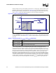
Figure 2-5. T
CONTROL
and Fan Speed Control
Pcont r ol _bas e
TDP
T
CASE
T
CASE
MAX
T
CASE
@
Pcont r ol _bas e
Power
Ther mal Profile
T
CASE
@ T
CONTROL
Pcont r ol
2
Fan speed control regi on
1
Pcont r ol _bas e
TDP
T
CASE
T
CASE
MAX
T
CASE
@
Pcont r ol _bas e
Power
Ther mal Profile
T
CASE
@ T
CONTROL
Pcont r ol
2
Fan speed control regi on
1
T
CASE
MAX
T
CASE
MAX@T
CONTROL
T
CASE
MAX@
Pcont rol _base
Pcont r ol _bas e
TDP
T
CASE
T
CASE
MAX
T
CASE
@
Pcont r ol _bas e
Power
Ther mal Profile
T
CASE
@ T
CONTROL
Pcont r ol
2
Fan speed control regi on
1
Pcont r ol _bas e
TDP
T
CASE
T
CASE
MAX
T
CASE
@
Pcont r ol _bas e
Power
Ther mal Profile
T
CASE
@ T
CONTROL
Pcont r ol
2
Fan speed control regi on
1
T
CASE
MAX
T
CASE
MAX@T
CONTROL
T
CASE
MAX@
Pcont rol _base
Table 2-7. Fan Speed Control, T
CONTROL
and T
DIODE
Relationship
Condition FSC Scheme
TDIODE = TCONTROL
FSC can adjust fan speed to maintain TDIODE = TCONTROL (low acoustic
region).
TDIODE > TCONTROL
FSC should adjust fan speed to keep TCASE at or below the Thermal Profile
specification (increased acoustic region).