
Intel Xeon Processor Multiprocessor Platform Design Guide


48
System Bus Routing
6.4.2.6 Topology 6: COMP[1:0] Signals
For details regarding termination of COMP[1:0] pins, please refer to the processor datasheet. Do
not wire COMP pins together; connect each pin to its own termination resistor.
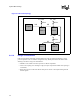
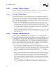
6.4.2.7 Topology 7: ODTEN Signal
The end processor in a 4-way processor system must have its on-die termination enabled. The
middle agent should disable the on-die termination. To enable, pull the ODTEN pin to a high state
by terminating it to V
CC_CPU
through a resistor. To disable, pull the ODTEN pin to a low state by
terminating it to ground through a resistor. There are two options for choosing the pull-up and pull-
down resistor values. While both options are suitable for this platform, Option 1 is preferred over
Option 2. The two available options are:
• Option 1 (preferred): Enable ODT (on-die termination) on Processor 0 (end processor) by
pulling up to V
CC_CPU
with a resistor that matches the motherboard trace impedance within ±
20%. Disable ODT on Processor 1, Processor 2, and Processor 3 by pulling down to V
SS
with
a resistor that matches the motherboard trace impedance within ± 20%. For example, since the
recommended nominal trace impedance is 50 Ω, resistor values within the range of 50 Ω ±
20% should be used for the pull-up and pull-down.
• Option 2: Enable ODT on Processor 0 (end processor) by pulling up to V
CC_CPU
with a 1 kΩ
resistor. Disable ODT on Processor 1, Processor 2, and Processor 3 by pulling down to V
SS
with a 1 kΩ resistor.
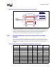
6.4.2.8 Topology 8: TESTHI[6:0] Signals
For each processor, all TESTHI[6:0] pins must be connected to V
CC_CPU
via pull-up resistors.
TESTHI[3:0] and TESTHI[6:5] may all be tied together at each processor and pulled up to
V
CC_CPU
with a single resistor, if desired. However, boundary scan testing will not be functional if
any TESTHI pins are connected together. TESTHI4 must always be pulled up independently from
the other TESTHI pins regardless of the usage of boundary scan. The TESTHI[6:0] signal group
must not be connected between processors. There are four options for choosing the pull-up and
pull-down resistor values. While four options are suitable for this platform, Intel recommends new
designs or designs undergoing design updates follow the trace impedance matching termination
guidelines given in Option 1a or Option 2a. The four available options are:
• Option 1a (preferred): All TESTHI[6:0] pins may be individually pulled-up to V
CC_CPU
with
resistors. For optimum noise margin, the pull-up resistor value should have a resistance value
within ± 20% of the impedance of the board transmission line traces. Since the recommended
nominal trace impedance is 50 Ω, use resistors that fall within the range of 50 Ω ± 20%.
• Option 1b: All TESTHI[6:0] pins may be individually pulled-up to V
CC_CPU
with 1 kΩ ± 5%
resistors.
• Option 2a (preferred): TESTHI[3:0] and TESTHI[6:5] may all be tied together and pulled up
to V
CC_CPU
with a single resistor. For optimum noise margin, the pull-up resistor value should
have a resistance value within ± 20% of the impedance of the board transmission line traces.
Since the recommended nominal trace impedance is 50 Ω, use resistors that fall within the
range of 50 Ω ± 20%. However, utilization of boundary scan test will not be functional if these
pins are connected together. TESTHI4 must always be pulled up independently from the other
TESTHI pins.
• Options 2b: TESTHI[3:0] and TESTHI[6:5] may all be tied together and pulled up to
V
CC_CPU
with a single 1 kΩ – 4.7 kΩ resistor if desired. However, utilization of boundary