
Intel Xeon Processor Multiprocessor Platform Design Guide


45
System Bus Routing
To protect the processors from damage in over-temperature situations, motherboard and/or chipset
logic must ensure that power to the processor core is removed within 0.5 seconds after the assertion
of THERMTRIP#. If power is applied to a processor when no thermal solution is attached, normal
leakage currents will cause the die temperature to rapidly rise to levels at which permanent silicon
damage is possible. This high temperature will cause THERMTRIP# to go active. For details
regarding the THERMTRIP# specification, refer to the processor datasheet.
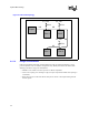
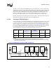
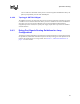
To avoid excessive undershoot seen at the processors, use dual termination on these four signals for
a 4-way configuration. Each processor's signals can be routed to its own receiver or they can be
wire-ORd together. If routed separately each signal must be terminated, but the signal can be
terminated at the receiver end only. Figure 6-9 illustrates the recommended topology.
If the functionality of any of these signals is not required, it is acceptable to not connect the pin (let
float).
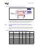
Trace Zo Trace Spacing L1 L2 L3 Rpu
50
Ω 10 mil 4–6” 1–12” 3” max 56 Ω ± 5%
Figure 6-9. Topology 1 for 4-Way Configuration
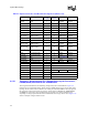
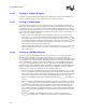
Figure 6-10. Example Voltage Translator Circuit
IOC
or
external
logic
CPU1
CPU3 CPU4CPU2
Rpu
Rpu
L1L1 L1 L2
L3
Vcc
CPU
L3
Vcc
CPU
From_Driver
To_Receiver
3904
3904
Vcc_of_Receiver
470 Ω
+- 5%
300 Ω
+- 5%
470 Ω
+- 5%
T1
T2
VT BOX
T1 = 10" max
T2 = 3" max