
Intel Xeon Processor Multiprocessor Platform Design Guide


14
Introduction
Convention/
Terminology
Definition
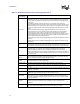
Flight Time
Flight time is a term in the timing equation that includes the signal propagation delay, any
effects the system has on the T
CO
of the driver, plus any adjustments to the signal at the
receiver needed to guarantee the setup time of the receiver. More precisely, flight time is
defined to be:
Time difference between a signal at the input pin of a receiving agent crossing the
switching voltage (adjusted to meet the receiver manufacturer’s conditions required for AC
timing specifications; e.g., ringback, etc.) and the output pin of the driving agent crossing
the switching voltage when the driver is driving a test load used to specify the driver’s AC
timings.
Maximum and Minimum Flight Time – Flight time variations can be caused by many
different parameters. The more obvious causes include variation of the board dielectric
constant, changes in load condition, crosstalk, power noise, variation in termination
resistance and differences in I/O buffer performance as a function of temperature, voltage
and manufacturing process. Some less obvious causes include effects of Simultaneous
Switching Output (SSO) and packaging effects.
Maximum flight time is the largest acceptable flight time a network will experience under all
conditions.
Minimum flight time is the smallest acceptable flight time a network will experience under
all conditions.
GTL+
GTL+ is the bus technology used by the Intel
Pentium
Pro processor. This is an incident
wave switching, open-drain bus with pull-up resistors that provide both the high logic level
and termination. It is an enhancement to the GTL (Gunning Transceiver Logic) technology.
ISI
Inter-symbol interference is the effect of a previous signal (or transition) on the
interconnect delay. For example, when a signal is transmitted down a line and the
reflections due to the transition have not completely dissipated, the following data
transition launched onto the bus is affected. ISI is dependent upon frequency, time delay of
the line, and the reflection coefficient at the driver and receiver. ISI can impact both timing
and signal integrity.
Manageability
Features
Circuits incorporated into the processor that allow system administrators to monitor
processor status and information including temperature, stepping, cache size, and more.
They are accessed through the System Management Bus.
Network
The network is the trace of a Printed Circuit Board (PCB) that completes an electrical
connection between two or more components.
Network Length The distance between agent 0 pin and the agent pin at the far end of the bus.
Overshoot
Maximum voltage observed for a signal at the device pad. Measured with respect to
V
CC_CPU.
Pad
The electrical contact point of a semiconductor die to the package substrate. A pad is only
observable in simulation.
Pin
The contact point of a component package to the traces on a substrate, like the
motherboard. Signal quality and timings can be measured at the pin.
Power-Good
“Power-Good” or “PWRGOOD” (an active high signal) indicates that all of the supplies and
clocks within the system are stable. PWRGOOD should go active a predetermined time
after system voltages are stable and should go inactive as soon as any of these voltages
fail their specifications.
Ringback
The voltage that a signal rings back to after achieving its maximum absolute value.
Ringback may be due to reflections, driver oscillations, or other transmission line
phenomena.
Setup Window
The time between the beginning of Setup to Clock (T
SU_MIN
) and the arrival of a valid clock
edge. This window may be different for each type of bus agent in the system.
Table 1-2. Platform Conventions and Terminology (Sheet 2 of 3)