
Intel Xeon Processor and Intel E7500/E7501Chipset Compatible Platform Design Guide

Intel
®
Xeon™ Processor and Intel
®
E7500/E7501 Chipset Compatible Platform Design Guide 117
Intel
®
82870P2 (P64H2)
8.1.4 Riser Card Topologies
The following guidelines are for systems that use a PCI-X riser card. A PCI-X riser card is a card
containing PCI-X slots that is plugged into a PCI-X connector. These guidelines assume a
PCI/PCI-X riser card with a 0.7 – 1.0 inch long trace length between slots. These simulations
require the clocks for each device and riser card slot to be tuned within 500 ps, or 2.85 in, of each
other. For the riser slot to also support a standard PCI/PCI-X adapter card, the tuning must also
include the adapter card length.
The following topologies denote an upper and lower portion to the length requirements. The PCI
specification requires the original 32-bit signals to have a card length of 0.75 to 1.5 inches. The
64-bit extension specifies the additional signals in the extension to have a length of 1.75 inches to
2.75 inches. Upper indicates the signals on the extension while Lower indicates signals lying in the
original 32-bit space.
In some of the riser card topologies, series resistors are required. These series resistors must be
placed on all signals listed in Table 8-2.
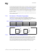
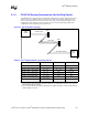
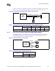
Figure 8-3 shows a PCI-X channel with a single connector used for a riser. If a 1 slot riser is used,
the channel can be run up to PCI-X 133 MHz. If a three slot riser is used, the channel can be run up
to PCI 66 MHz.
Figure 8-3. PCI-X Riser Card Topology
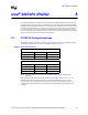
Table 8-6. PCI-X Riser Card Length Requirements
Configuration
Intel
®
P64H2 to Riser
Lower Upper
PCI-X 133 MHz, 1 slot riser 1.0” – 7.25” 1.0” – 6.5”
PCI-X 66 MHz, 3 slot riser 1.0” – 8.25” 1.0” – 3.8”
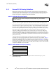
Intel
®
P64H2
P64H2 to Riser
Ris er