
Intel Xeon Processor and Intel E7500/E7501Chipset Compatible Platform Design Guide


Intel
®
Xeon™ Processor and Intel
®
E7500/E7501 Chipset Compatible Platform Design Guide 101
Memory Interface Routing Guidelines
6.9 2.5 V Decoupling Requirements
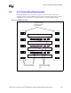
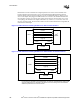
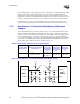
Decouple the DIMM connectors as shown in Figure 6-19. Place six ceramic 0.1 µF (0603)
capacitors between each pair of DIMM connectors. Place ten Tantalum 100 µF capacitors around
the DIMM connectors per channel, keeping them within 0.5 inch of the DIMM connectors.
Figure 6-19. DIMM Decoupling
DIMM
DIMM
DIMM
DIMM
10 Tantulum 100 µF
Capacitors/Channel
Around DIMMs
6 Ceramic 0.10 µF Caps
(0603) Between DIMM
Pairs
2 Vias Per Capacitor to
Internal Ground Plane