
64-bit Intel Xeon Processorwith 1MB L2 Cache Thermal/Mechanical Design Guidelines
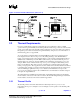
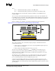
Table Of Contents

Thermal/Mechanical Reference Design
R
18 64-bit Intel
®
Xeon™ Processor MP with 1 MB L2 Cache
Thermal/Mechanical Design Guidelines
Ψ
CA
= (T
CASE
– T
LA
) / TDP = (68 – 45) / 85 = 0.27 °C/W
To determine the required heatsink performance, a heatsink solution provider would need to
determine Ψ
CS
performance for the selected TIM and mechanical load configuration. If the heatsink
solution was designed to work with a TIM material performing at Ψ
CS
≤ 0.05 °C/W, solving for
equation 2 from above, the performance of the heatsink would be:
Ψ
SA
= Ψ
CA
− Ψ
CS
= 0.27 − 0.05 = 0.22 °C/W
If the local processor ambient temperature is assumed to be 40°C, the same calculation can be
carried out to determine the new case-to-ambient thermal resistance:
Ψ
CA
= (T
CASE
– T
LA
) / TDP = (68 – 40) / 85 = 0.33 °C/W
It is evident from the above calculations that, a reduction in the local processor ambient temperature
has a significant positive effect on the case-to-ambient thermal resistance requirement.
2.3.3 Chassis Thermal Design Considerations
2.3.3.1 Chassis Thermal Design Capabilities and Improvements
One of the critical parameters in thermal design is the local ambient temperature assumption of the
processor. Keeping the external chassis temperature fixed, internal chassis temperature rise is the
only component that can affect the processor local ambient temperature. Every degree gained at the
local ambient temperature directly translates into a degree relief in the processor case temperature.
Given the thermal targets for the processor, it is extremely important to optimize the chassis design
to minimize the air temperature rise upstream to the processor (T
RISE
), hence minimizing the
processor local ambient temperature. Please refer to Appendix B.
The heat generated by components within the chassis must be removed to provide an adequate
operating environment for both the processor and other system components. Moving air through the
chassis brings in air from the external ambient environment and transports the heat generated by the
processor and other system components out of the system. The number, size and relative position of
fans, vents and other heat generating components determine the chassis thermal performance, and
the resulting ambient temperature around the processor. The size and type (passive or active) of the
thermal solution and the amount of system airflow can be traded off against each other to meet
specific system design constraints. Additional constraints are board layout, spacing, component
placement, and structural considerations that limit the thermal solution size.
In addition to passive heatsinks, fan heatsinks and system fans, other solutions exist for cooling
integrated circuit devices. For example, ducted blowers, heat pipes and liquid cooling are all capable
of dissipating additional heat. Due to their varying attributes, each of these solutions may be
appropriate for a particular system implementation.
To develop a reliable, cost-effective thermal solution, thermal characterization and simulation
should be carried out at the entire system level, accounting for the thermal requirements of each
component. In addition, acoustic noise constraints may limit the size, number, placement, and types
of fans that can be used in a particular design.