
64-bit Intel Xeon Processorwith 1MB L2 Cache Thermal/Mechanical Design Guidelines
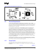
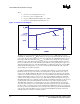
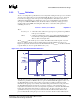
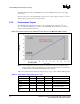
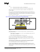
Table Of Contents

Thermal/Mechanical Reference Design
R
16 64-bit Intel
®
Xeon™ Processor MP with 1 MB L2 Cache
Thermal/Mechanical Design Guidelines
Table 2-3. Fan Speed Control, T
CONTROL
and T
DIODE
Relationship
Condition FSC Scheme
TDIODE ≤ TCONTROL FSC can adjust fan speed to maintain TDIODE ≤ TCONTROL (low acoustic region).
TDIODE > TCONTROL FSC should adjust fan speed to keep TCASE at or below the Thermal Profile
specification (increased acoustic region).
There are many different ways of implementing fan speed control, including FSC based on
processor ambient temperature; FSC based on processor thermal diode temperature (T
DIODE
) or a
combination of the two. If FSC is based only on the processor ambient temperature, low acoustic
targets can be achieved under low ambient temperature conditions. However, the acoustics cannot
be optimized based on the behavior of the processor temperature. If FSC is based only on the
thermal diode, sustained temperatures above T
CONTROL
, drives fans to maximum RPM. If FSC is
based both on ambient and thermal diode, ambient temperature can be used to scale the fan RPM
controlled by the thermal diode. This would result in an optimal acoustic performance. Regardless
of which scheme is employed, system designers must ensure that the Thermal Profile specification
is met when the processor diode temperature exceeds the T
CONTOL
value for a given processor.
2.3.2 Processor Thermal Characterization Parameter
Relationships
The idea of a “thermal characterization parameter”, Ψ (psi), is a convenient way to characterize the
performance needed for the thermal solution and to compare thermal solutions in identical
conditions (heating source, local ambient conditions). A thermal characterization parameter is
convenient in that it is calculated using total package power, whereas actual thermal resistance, θ
(theta), is calculated using actual power dissipated between two points. Measuring actual power
dissipated by the heatsink is difficult since some of the power is dissipated via heat transfer into the
socket and board. Be aware, however, of the limitations of lumped parameters such as Ψ when it
comes to a real design. Heat transfer is a three-dimensional phenomenon that can rarely be
accurately and easily modeled by lump values.
The case-to-local ambient thermal characterization parameter value (Ψ
CA
) is used as a measure of
the thermal performance of the overall thermal solution that is attached to the processor package. It
is defined by the following equation, and measured in units of °C/W:
Ψ
CA
= (T
CASE
- T
LA
) /
TDP
Equation 3
Where:
Ψ
CA
= Case-to-local ambient thermal characterization parameter (°C/W).
T
CASE
= Processor case temperature (°C).
T
LA
= Local ambient temperature in chassis at processor (°C).
P
D
= TDP dissipation (W) (assumes all power dissipates through the integrated heat
spreader (IHS)).
The case-to-local ambient thermal characterization parameter of the processor, Ψ
CA
, is comprised of
Ψ
CS
, the TIM thermal characterization parameter, and of Ψ
SA
, the sink-to-local ambient thermal
characterization parameter:
Ψ
CA
= Ψ
CS
+ Ψ
SA
Equation 4