
603 Pin Socket Design Guidelines

603 Pin Socket Design Guidelines
R
17
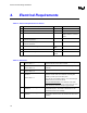
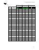
Socket electrical requirements are measured from the socket-seating plane of the processor test vehicle
(PTV) to the component side of the socket PCB to which it is attached. All specifications are maximum
values (unless otherwise stated) for a single socket pin, but includes effects of adjacent pins where
indicated. Pin and socket inductance includes exposed pin from mated contact to bottom of the
processor pin field.
4.1. Electrical Resistance:
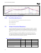
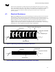
Figure 4-1 and Figure 4-2 show the proposed methodology for measuring the final electrical resistance.
The methodology requires measuring interposer flush-mounted directly to the motherboard fixtures, so
that the pin shoulder is flush with the motherboard, to get the averaged jumper resistance, Rjumper. The
Rjumper should come from a good statistical average of 30 interposer fixtures flush mounted to a
motherboard fixture. The same measurements are then made with an interposer fixture mounted on a
supplier’s socket, and both are mounted on a motherboard fixture; this provides the R
Total
. The resistance
requirement, R
Req
, can be calculated for each chain as will be explained later.
Interposer shoulder
Interposer pin
Motherboard
Socket contact
interposer
Shorting bar
+V
+I
-V
-I
Figure 4-1: Methodology for Measuring Total Electrical Resistance.
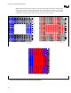
Interposer shoulder
Motherboard
interposer
Shorting bar
+V
+I
-V
-I
Figure 4-2: Methodology for Measuring Electrical Resistance of the Jumper