
Intel Xeon Processor Multiprocessor Platform Design Guide

37
System Bus Routing
6.4.1 Topology and Routing
Design recommendations will be presented first followed by design considerations. The layout
guidelines given in this section are based on specific chipset (I/O buffer, package, and loading) and
motherboard properties. Complete simulation and hardware validation is necessary to ensure a
robust design.
6.4.1.1 Design Recommendations
Below are the design recommendations for the data, address, strobes, and common clock signals.
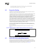
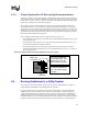
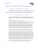
The 4-way processor topology requires that the chipset be at one end of the bus and that no
motherboard contribution to the stub length of the processors in the middle of the bus exists.
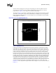
Figure 6-4 shows a schematic of an Intel Xeon processor MP and Intel Xeon processor MP with up
to 2-MB L3 cache on the 0.13 micron process quad processor daisy chain topology with the chipset
at the end. A U-turn may exist between processor 2 and processor 3.
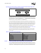
The motherboard trace impedance should be between 47 Ω–50 Ω ± 10%. The traces should
maintain a greater than three to one “edge-to-edge spacing” versus “trace to reference plane
height” ratio (see Figure 6-5). As the traces pass through the pin fields, the 3:1 requirement may
not be achievable. In these areas where the 3:1 ratio is not possible, the separation should be
maximized and the distance of the violation should be minimized. Specifically, when routing
through the 603-pin socket expand to a 3:1 ratio whenever possible. Do not keep a tighter spacing
ratio the entire length of the socket. However, do not route through the V
CC_CPU
and V
SS_CPU
pin
field as this also has a great potential for noise coupling. Trace spacing to height ratio of 3 to 1
above the reference plane ensures a low crosstalk coefficient. All the effects of crosstalk are
difficult and tedious to simulate. Intel has performed extensive simulation and experimentation on
the effects of crosstalk to more accurately predict these effects. The timing and layout guidelines
for processor have been created with the assumption of 3:1 trace spacing to height above reference
plane ratio. A smaller ratio would have a negative impact on both timing and noise margins due to
crosstalk.
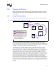
Figure 6-4. 4-Way Processor System Bus Topology
Chip
Set
Proc 1
*There is No Motherboard
PCB Stub For Middle Agents
Proc 2
Length L2
Length L1
Proc 3
Proc 4
Length L3
Length L4
Package trace
Motherboard PCB trace
PD PD
PD
PD
PD = processor delta
CD = chipset delta
CD