
Intel Xeon Processor Multiprocessor Platform Design Guide


116
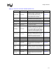
Design Checklist
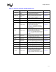
Processor Pin Signal Type Pin Connection Section No.
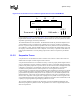
BNR# Common Clock
Connect to all system bus agents, and the
chipset if supported. Wired-OR signal.
All wired-OR signals should have AC
termination to VCC_CPU at the middle agents
(see Figure 6-7). The termination should be
located as close as possible to the processor
pins with no stubs.
Section 6.4.1
BPRI# Common Clock Connect to all system bus agents. Section 6.4.1
BR[0]# Common Clock
Connect to all system bus agents. Swizzle
signals between processors.
BR0# should be connected to the chipset.
Terminate using a 50
Ω pull-up resistor at the
processor end.
Section 6.4.1
BR[3:1]# Common Clock
Connect to all 4 processors. Swizzle signals
between processors.
Dual terminations using a 50
Ω pull-up resistor.
Section 6.4.1
COMP[1:0] Power/Other Refer to processor datasheet. Section 6.4.2
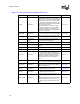
D[63:0]#
Source synch
AGTL+
Connect to all system bus agents. Balance
signal lengths within strobe group.
Section 6.4.1
DBI[3:0]#
Source synch
AGTL+
Connect to all system bus agents. Balance
signal lengths within strobe group.
Section 6.4.1
DBSY# Common Clock Connect to all system bus agents. Section 6.4.1
DEFER# Common Clock Connect to all system bus agents. Section 6.4.1
DP[3:0] Common Clock Connect to all system bus agents. Section 6.4.1
DRDY# Common Clock Connect to all system bus agents. Section 6.4.1
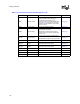
Table 11-1. Processor Connection Checklist (Sheet 2 of 5)