
Intel Xeon Processor and Intel E7500/E7501Chipset Compatible Platform Design Guide


Intel
®
Xeon™ Processor and Intel
®
E7500/E7501 Chipset Compatible Platform Design Guide 257
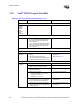
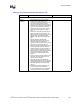
Layout Checklist
USB
General
Guidelines
• Route all traces over continuous planes
(ground) with no interruptions. Avoid
crossing over anti-etch if possible. Crossing
over anti-etch (plane splits) increases
inductance and radiation levels by forcing a
greater loop area. Likewise, avoid changing
layers with high-speed traces. (Applies to
USB signals, high-speed clocks, as well as
slower signals that might be coupling to
them.)
• Keep traces at least 50 mils away from the
edge of the reference ground plane. This
helps prevent the coupling of the signal onto
adjacent wires, and helps prevent free
radiation of the signal from the edge of the
PCB.
• Maintain parallelism between USB
differential signals with the trace spacing
needed to achieve 90
Ω differential
impedance. (Recommended: 5 on 6 spacing
with 4-layer 4.5-mil prepreg stack-up).
• Minimize the length of high-speed clock and
periodic signal traces that run parallel to
USB signal lines to minimize crosstalk. The
minimum recommended spacing to clock
signals is 20 mils, though it is recommended
to keep clocks and PCI traces at least
50 mils from the USB differential pairs if
possible.
• Use 20 mil minimum spacing between USB
signal pairs and other signal traces. This
helps to prevent crosstalk.
• USB signal pair traces should be trace
length matched. Max trace length mismatch
between USB signal pair (such as USBP2P
and USBP2N) should be no greater than
150 mils.
• No termination resistors needed for USB.
ICH3-S has internal 15 k
Ω resistors.
• 47 pF parallel capacitors may be placed as
close to the USB connector as possible.
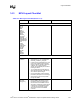
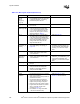
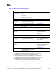
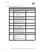
Table 14-4. Intel
®
ICH3-S Layout Checklist (Sheet 4 of 4)
Checklist Items Recommendations Comments