
Intel Xeon Processor and Intel E7500/E7501Chipset Compatible Platform Design Guide

Intel
®
Xeon™ Processor and Intel
®
E7500/E7501 Chipset Compatible Platform Design Guide 235
Schematic Checklist
EE_DOUT • Connect to EE_DIN of EEPROM. (Input
from EEPROM perspective and output from
ICH3-S perspective.)
• If unused, leave No Connect.
• ICH3-S contains an integrated
pull-up resistor for this signal.
EE_DIN • Connect to EE_DOUT of EEPROM. (Ouput
from EEPROM perspective and input from
ICH3-S perspective.)
• If unused, leave No Connect.
• ICH3-S contains an integrated
pull-up resistor for this signal.
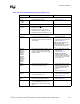
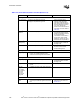
PCI Interface
PERR#
SERR#
PLOCK#
STOP#
DEVSEL#
TRDY#
IRDY#
FRAME#
REQ[4:0]#
GPIO[0]/REQ[A]#
GPIO[1]/REQ[B]#/
REQ[5]#
• 8.2 k
Ω ± 5% pull-up to 3.3 V, or a
2.7 k
Ω± 5% pull-up to 5 V.
• See the
PCI Local Bus
Specification, Revision 2.2
for
pull-up recommendations for
3.3 V and 5 V.
PCIRST# • Depending on the load, this signal may have
to be buffered.
• Improves Signal Integrity.
GNT[4:0]# • No external pull-up resistors are required on
PCI GNT signals. However, if external pull-
up resistors are implemented, they must be
pulled up to 3.3 V.
• These signals are actively
driven by the ICH3-S.
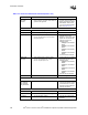
PME# • No extra pull-up needed. • This signal has integrated pull-
up of 18 k
Ω to 42 kΩ.
GNT[A]# /GPIO[16]
GNT[B]#/ GNT[5]#/
GPIO[17]
• No extra pull-up needed. • These signals have integrated
pull-ups of 24 k
Ω.
• GNT[A] has an added strap
function of “top block swap.”
The signal is sampled on the
rising edge of PWROK. Default
value is high or disabled due to
pull-up. A Jumper to a pull-
down resistor can be added to
manually enable the function.
Power Decoupling
V_CPU_IO • Connect to VCC_CPU.
• Use one 0.1 µF decoupling capacitor.
• Refer to Section 11.4.4.
VCCRTC • No clear CMOS jumper on VCCRTC. Use a
jumper on RTCRST# or a GPI, or use a safe
mode strapping for Clear CMOS.
• Requires one 0.1 µF decoupling capacitor.
• Refer to Section 11.4.4.
VCC3_3 • Use six 0.1 µF decoupling capacitors. • Refer to Section 11.4.4.
VCCSus3_3 • Use two 0.1 µF decoupling capacitors. • Refer to Section 11.4.4.
VCC1_8 • Use four 0.1 µF decoupling capacitors. • Refer to Section 11.4.4.
VCCSus1_8 • Use one 0.1 µF decoupling capacitor. • Refer to Section 11.4.4.
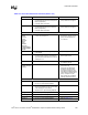
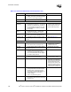
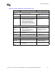
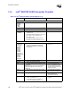
Table 13-3. Intel
®
ICH3-S Schematic Checklist (Sheet 4 of 6)
Checklist Items Recommendations Comments