
Intel Xeon Processor and Intel E7500/E7501Chipset Compatible Platform Design Guide


Platform Power Delivery Guidelines
190 Intel
®
Xeon™ Processor and Intel
®
E7500/E7501 Chipset Compatible Platform Design Guide
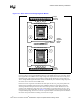
11.2.8 Power Planes
VCC_CPU static and transient tolerances of the processor, and the corresponding voltage regulator
tolerances assume power distribution paths with round trip resistances no greater than 300 µ
Ω and
inductances any greater than 100 pH. Power must be distributed as a plane. This plane can be
constructed as an island on a layer used for other signals, on a supply plane with other power
islands, or as a dedicated layer of the PCB. Processor power should never be distributed by traces
alone.
Because processor voltage is unique to most system designs, a voltage island will probably be the
most cost-effective means of distributing power to the processors. This island from the source of
power to the load should not have any breaks, so as to minimize inductance in the plane. It should
also completely surround all of the pins of the source and all of the pins of the load.
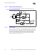
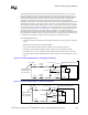
The imperfections of the power planes themselves may introduce unwanted resistance and
inductance into the power distribution system. Assuming layer thickness is smaller than skin depth,
the metal layer resistance can be calculated as:
Where
ρ is the copper resistivity (ρ = 0.667 mΩ-mil), l, w, and t are the length, width and thickness
of the metal layer, respectively.
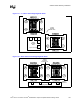
The loop inductance can be calculated as:
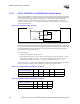
Where N is the number of VCC_CPU/VSS_CPU planes. To minimize parasitic layer inductance, it
is important to reduce the distance from decoupling capacitors to the processor socket (reducing l)
and to use islands for power distribution (increasing w). To reduce h, it is recommended to select
the VCC_CPU/VSS_CPU planes in the layer stack-up that are interleaved and have small spacing
in between. As a practical matter, it is impossible to get the requisite baseboard inductance without
locally dedicating at least 4 planes to carry power from the baseboard capacitors to the power pins
of the processor.
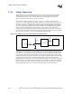
There are impedance consequences for signals that cross over or under the edges of the Power
Island that exists on another layer. While neither of these may be necessary for most designs, there
are two reasonable options to consider which can protect a system from these consequences:
• Processor power islands can be isolated from signals by one of the solid power plane layers
such as the ground layer. This forces a particular stack-up model.
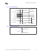
• Another option that helps, but does not completely eliminate radiation effects, is to decouple
the edges of the processor power islands to ground on regular intervals of about 1 inch using
good high-frequency decoupling capacitors (1206 packages). This requires more components
but does not require any particular board stack-up.
tw
l
R
⋅
⋅=
ρ
w
l
h
t
)1(mil
pH
9.31
−⋅
⋅
⋅=
Nw
hl
L