
Voltage Regulator Module (VRM) and Enterprise Voltage Regulator-Down (EVRD) 10.1 Design Guidelines


Output Indicators
28 Voltage Regulator Module (VRM) and Enterprise Voltage
Regulator-Down (EVRD) 10.1 Design Guidelines
It is recommended that hysteresis be designed into the thermal sense circuit to prevent a scenario in
which the VR_hot# signal is rapidly being asserted and de-asserted.
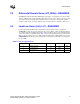
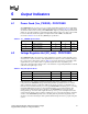
6.3 Load Indicator Output (Load Current) - PROPOSED
The VRM/EVRD may have an output with a voltage (Load Current) level that varies linearly with
the VRM/EVRD output current. The PWM controller supplier may specify a voltage-current
relationship consistent with the controller’s current sensing method. Baseboard designers may
route this output to a test point for system validation.
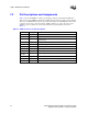
6.4 VRM Present (VRM_pres#) - EXPECTED
The VRM should have the VRM_pres# signal. This signal is an output signal used to indicate to the
system that a VRM is plugged into the socket. VRM_pres# is an open-collector/drain or equivalent
signal. Table 6-3 shows the VRM_pres# pin specification. It is EXPECTED that the pull-up
resistor will be located on the baseboard and will not be integrated into the VRM.
§
Table 6-3. VRM_pres Specifications
Symbol Parameter Min Max Units
I
OL
Output Low Current 0 4 mA
V
OH
Output High Voltage 0.8 5.5 V
V
OL
Output Low Voltage 0 0.4 V