
Intel Xeon Processor Multiprocessor Platform Design Guide

68
Processor Power Distribution Guidelines
8.7.2.4 Voltage Regulator Remote Sense Connection
The system board is to include a positive and a negative SENSE input for each voltage regulator
module. The round trip trace resistance should not be greater than one ohm. These voltage sense
lines draw little current and there should be only a minute voltage drop from the remote sense
connection and the voltage regulators.
In a multiprocessor system the SENSE lines from the voltage regulator modules should be routed
to a point in the middle of and equidistant from all processors. At this remote sense point all
positive SENSE lines should be tied together and connected to V
CC_CPU
and all negative SENSE
lines should be tied together and connected to V
SS_CPU
.
All SENSE lines should be routed directly between the remote sense point and the voltage
regulator and should not exceed 5 inches in trace length. If the SENSE lines are routed parallel to
signal lines, the SENSE lines should be shielded.
8.7.2.5 Voltage Regulator Module ISHARE Connection
If voltage regulator modules are used it is necessary that the ISHARE lines of the modules be
connected. The round trip resistance of this connection should be less than 1 Ω. The I
SHARE
connection traces should be shielded from or separated from noisy signal traces.
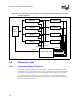
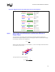
8.7.2.6 Voltage Regulator Module OUTEN Connection
The voltage regulators' OUTEN input is used to disable the regulators' output voltage. The system
designer should disable the output of the voltage regulator in a multiprocessor system when
processors with different voltage settings are installed. The block diagram, Figure 8-1, shows this
implementation based on VID [4:0] signals. Note that the VID lines are pulled up internal to the
voltage regulators. No pull-ups are allowed on the baseboard. If the designer adds pull-ups on the
baseboards, voltage-sequencing problems can occur with unpredictable results.
8.8 Power Planes
V
CC
static and transient tolerances of the processor, and the corresponding voltage regulator
tolerances assume power distribution paths with round trip resistances no greater than 300 mΩ and
inductances any greater than 100 pH. Power must be distributed as a plane. This plane can be
constructed as an island on a layer used for other signals, on a supply plane with other power
islands, or as a dedicated layer of the PCB. Processor power should never be distributed by traces
alone.
Due to the fact that processor voltage is unique to most system designs, a voltage island will
probably be the most cost-effective means of distributing power to the processors. This island from
the source of power to the load should not have any breaks, so as to minimize inductance in the
plane. It should also completely surround all of the pins of the source and all of the pins of the load.
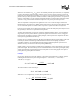
8.8.1 Layer Stack-Up
Intel recommends an absolute minimum of two ounce copper power plane for both V
CC
and V
SS
.
The goal should be at 3.5 ounces or more for four processor systems. This can be implemented
using multiple layers as shown in example Figure 8-2.