
Intel Xeon Processor Multiprocessor Platform Design Guide

107
System Theory
System Theory 10
This section provides in-depth information about signal technology and system signal interference.
10.1 AGTL+ Logic
AGTL+ is the electrical system bus technology. It is an incident wave switching, open-drain bus
with integrated pull-up resistors (p-channel FETs) that provide both the high logic level and the
termination.
The end agents on the system bus will always have their termination on. Middle agents' pull-ups
will turn on only when needed to drive a signal to its high state. The ODTEN pin on the processor
will be used to determine whether a processor is an end agent and thus needs to enable its
termination. It is up to the baseboard designer to pull this pin to the appropriate logic level (high to
enable).
10.2 Inter-Symbol Interference
Inter-symbol interference (ISI) is the effect of a previous signal (or transition) on the interconnect
delay. When a signal is transmitted down a transmission line and the reflections due to the
transition have not completely dissipated, the following data transition launched onto the bus is
affected. ISI can impact both the timing and the signal integrity. ISI is dependent upon frequency,
time delay of the line, and the reflection coefficient at the driver and receiver. Thus, ISI is a major
concern in any high-speed design where the period is smaller than the delay of the transmission
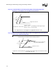
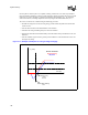
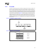
line. Figure 10-1 shows an example of how ISI can affect timing. In this example the starting
voltage of the driver is different from the idle state starting voltage. This figure illustrates the ISI
effect on both timing and signal integrity.
One method of capturing most of the timing impact due to ISI is to perform parameter sweeps at
the fastest bus period, and then at 2Xand 3X multiples of the fastest bus period. For example, if the
fastest frequency at which the bus will operate is 400 MHz, then the pulse duration of a single bit is
2.5 ns (5 ns period). The data pattern should be repeated with pulse durations of 5 ns and 7.5 ns
(10 ns and 15 ns periods). This represents the following data patterns transitioning at the highest
bus rate.
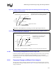
01010101010101
00110011001100
00011100011100
The worst-case results of these patterns can be used to produce the phase 1 solution space. The
maximum difference in flight time between these patterns produces a first order approximation of
the ISI impact.
The final solution space must account for the full ISI variations. This can be done by performing
targeted simulations at the edges of the phase 2 solution space using a long pseudo-random pulse
train. If the timing impact due to ISI does not violate any timing or signal integrity specifications,