
Intel Xeon Processor and Intel E7500/E7501Chipset Compatible Platform Design Guide

Intel
®
Xeon™ Processor and Intel
®
E7500/E7501 Chipset Compatible Platform Design Guide 237
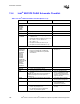
Schematic Checklist
RTC
VBIAS • Use one 0.047 µF capacitor. • For noise immunity on VBIAS
signal.
• Refer to Figure 9-11.
RTCRST • Refer to Section 9.6.8.
RTCX1
RTCX2
• Connect a 32.768 kHz Crystal Oscillator
across these pins with a 10 M
Ω resistor.
Decouple each signal dependant upon the
crystal oscillator’s characteristics.
• RTCX1 may optionally be driven by an
external oscillator instead of a crystal.
These signals are 1.8 V only, and must not
be driven by a 3.3 V source.
• Refer to Section 9.6.1 and
Section 9.6.3.
System Management
SMBDATA
SMBCLK
SMLINK[1:0]
• Connect SMBCLK to SMLink0 and
SMBDATA to SMLink1.
• Require external pull-up resistors,
dependant upon bus capacitance and
termination power plane.
• Refer to Section 9.5.
• Value of pull-up resistors
determined by line load, from
Section 9.5.4.
SMBALERT#/
GPIO[11]
• See GPIO section if SMBALERT# not
implemented.
INTRUDER# • 10 k
Ω ± 5% pull-up to VCCRTC (VBAT) if
not needed.
• Refer to Section 9.6.8.
USB
USBRBIAS • 18.2 Ω ± 1% pull-down to ground.
USBP[5:0]P
USBP[5:0]N
• No external resistors are required. • Integrated 15 k
Ω pull-down,
effective output driver
impedance of 45
Ω provided.
OC[5:0]# • If not used: 10 k
Ω ± 5% pull-up to
VCCSUS3_3.
• Inputs must not float.
NOTES:
1. LINT1 and LINT0 map to INTR and NMI in the ICH3-S.
Table 13-3. Intel
®
ICH3-S Schematic Checklist (Sheet 6 of 6)
Checklist Items Recommendations Comments