
Intel Xeon Processor and Intel E7500/E7501Chipset Compatible Platform Design Guide

Schematic Checklist
234 Intel
®
Xeon™ Processor and Intel
®
E7500/E7501 Chipset Compatible Platform Design Guide
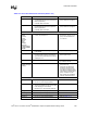
Host Side / Device
Side Cable
Detection
• Connect IDE pin PDIAG#/CBLID# to an
ICH3-S GPI pin. Connect a 10 k
Ω resistor to
ground on the signal line.
• The 10 k
Ω resistor to ground
prevents GPI from floating if no
devices are present on either
IDE interface. Allows use of
3.3 V and 5 V tolerant GPIOs.
• Refer to Section 9.1.2.1.
Interrupt Interface
APICCLK • Pull-down directly to ground.
APICD[1:0] • 10 k
Ω ± 5% pull-down to ground.
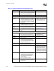
PIRQ[D:A]# • These signals require a pull-up resistor.
•2.7 k
Ω ± 5% pull-up to 5 V or an 8.2 kΩ±
5%
pull-up to 3.3 V.
• Each PIRQx# line has a
separate Route Control
Register. In APIC mode, these
signals are connected to the
internal I/O APIC in the
following fashion:
– PIRQ[A]# is connected to
IRQ16.
– PIRQ[B]# is connected to
IRQ17.
– PIRQ[C]# is connected to
IRQ18.
– PIRQ[D]# is connected to
IRQ19.
This frees the ISA interrupts.
PIRQ[H:E]#/
GPIO[5:2]
• These signals require a pull-up resistor.
•2.7 k
Ω ± 5% pull-up to VCC_5 or an
8.2 k
Ω± 5% pull-up to 3.3 V.
• These signals are connected to
the internal I/O APIC in the
following fashion:
– PIRQ[E]# is connected to
IRQ20.
– PIRQ[F]# is connected to
IRQ21.
– PIRQ[G]# is connected to
IRQ22.
– PIRQ[H]# is connected to
IRQ23.
This frees the ISA interrupts.
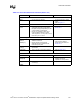
SERIRQ • 8.2 k
Ω ± 5% pull-up to 3.3 V. • Open drain signal.
LAN Interface
LAN_CLK,
LAN_RXD[2:0],
LAN_TXD[2:0],
LAN_RSTSYNC
• Connect to Platform LAN Connect Device. • Refer to Section 9.7.
• LAN Connect Interface Signals
can be left as NC if not used
because the Input buffers are
internally terminated.
Miscellaneous Signals
SPKR • No extra pull-up resistors. • Refer to Section 9.2.
TP[0] • 8.2 k
Ω – 10 kΩ pull-up to VCCSUS3_3.
AC_SDOUT • No extra pull-down needed. • This ball has a weak internal
pull-down.
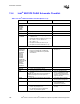
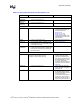
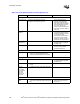
Table 13-3. Intel
®
ICH3-S Schematic Checklist (Sheet 3 of 6)
Checklist Items Recommendations Comments