
Intel Xeon Processor and Intel E7500/E7501Chipset Compatible Platform Design Guide


Intel
®
Xeon™ Processor and Intel
®
E7500/E7501 Chipset Compatible Platform Design Guide 191
Platform Power Delivery Guidelines
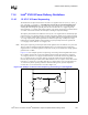
In either case, for controlling emissions, all planes and islands should be well decoupled. The exact
board layout, and the chassis design will determine the amount of decoupling required for
controlling emissions. Proper designs will incorporate additional pads for capacitors to be added in
case they are found to be necessary during EMI testing.
Signals routed over power islands or islands in the ground plane create a discontinuity in the return
path of that signal. This discontinuity can have detrimental effects on the timing and signal quality
of that signal and other signals referencing the same planes. Avoid routing signals over splits in
power planes or ground planes at all times.
11.2.9 Processor Decoupling
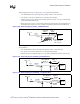
The inductance of the system due to cables and power planes slows the power supply's ability to
respond quickly to a current transient. Decoupling a power plane can be broken into several
independent parts. The closer to the load the capacitor is placed, the more inductance is bypassed.
By bypassing the inductance of leads, power planes etc., less capacitance is required. However,
closer to the load there is less room for capacitance. Therefore, trade-offs must be made.
Using capacitors with the wrong ESR, ESL, and/or package can mitigate their intended operation
and result in violations of the processor power specifications. For example, capacitors with the
wrong package or with ESR/ESL properties in excess of the recommendations may have increased
transient response times that are unable to respond to the processor’s current transients.
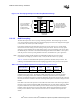
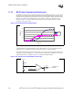
11.2.9.1 High-Frequency Decoupling
The system boards should include high-frequency capacitors as close to the socket power and
ground pins as possible. A motherboard’s power and ground plane inductance can cancel the
usefulness of these low-inductance capacitors if they are not placed close to the socket. Place as
many capacitors as possible in the socket cut out area. Table 11-4 lists the recommended high-
frequency capacitance for Intel Xeon processor baseboards.
If there is difficulty in placing the 1210 size 22 µF capacitors (as listed in Table 11-4), replace those
with a same number of 1206 size 10 µF capacitors using similar placement guidelines. However,
increase the number of OS-CONs (as defined in Table 11-5) from 10 to 11 to compensate for the
reduced total capacitance.
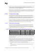
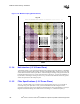
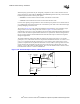
In addition, high-frequency decoupling may be required for signal integrity. System boards
designed using striplines with VCC_CPU and ground references should not require high-frequency
decoupling beyond the recommendations listed in Table 11-4. For systems using microstrip
configurations, a return path discontinuity will exist between the processor and the baseboard due
to the baseboard traces having only one reference plane. These systems should distribute
decoupling capacitors, as shown in Figure 11-16 and described as follows:
• 4 minimum, 6 preferred 1 µF capacitors with 0805 packages distributed evenly over the data
lines.
• 3 minimum, 4 preferred 0.1 µF capacitors with 0603 packages distributed evenly over the
address and control lines.
Table 11-4. Processor High-Frequency Capacitance Recommendations Per Processor
High-Frequency Capacitance Quantity ESR ESL
0805 Package, 1 µF (Signal Integrity) 4 8 mΩ 702 pH
0603 Package, 0.1 µF (Signal Integrity) 3 6 m
Ω 630 pH
1210 Package, 22 µF (Power Decoupling) 20 10 m
Ω 1.1 nH