
VRM 9.1 DC-DC Converter Design Guidelines

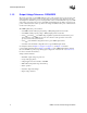
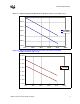
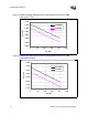
Table Of Contents
- 1 Electrical Specifications
- 1.1 Output Requirements
- 1.1.1 Voltage and Current - REQUIRED
- 1.1.2 Maximum Ratings - EXPECTED
- 1.1.3 Output Voltage Tolerance - REQUIRED
- 1.1.4 No-Load Operation - REQUIRED
- 1.1.5 Turn-on Response Time - EXPECTED
- 1.1.6 Overshoot and Undershoot at Turn-On or Turn-Off - REQUIRED
- 1.1.7 Converter Stability - REQUIRED
- 1.1.8 Current Sharing - REQUIRED
- 1.2 Input Voltage and Current
- 1.3 Control Inputs - REQUIRED
- 1.4 Remote Sense (VO-sen+, VO-sen-) - EXPECTED
- 1.5 Power Good Output (PWRGD) - REQUIRED
- 1.6 VRM Present (VRM-pres) - EXPECTED
- 1.7 Efficiency - PROPOSED
- 1.8 Isolation - PROPOSED
- 1.9 Fault Protection
- 1.1 Output Requirements
- 2 Module Layout Guidelines
- 3 Environmental Conditions
- 3.1 Operating Temperature - PROPOSED
- 3.2 VRM Board Temperature - REQUIRED
- 3.3 Non-Operating Temperature - PROPOSED
- 3.4 Humidity - PROPOSED
- 3.5 Altitude - PROPOSED
- 3.6 Electrostatic Discharge - PROPOSED
- 3.7 Shock and Vibration - PROPOSED
- 3.8 Electromagnetic Compatibility - PROPOSED
- 3.9 Reliability - PROPOSED
- 3.10 Safety - PROPOSED
Electrical Specifications
10 VRM 9.1 DC-DC Converter Design Guidelines
Figure 1-3. VRM 9.1 Regulation Requirement for 64-bit Intel
®
Xeon™ Processor MP
Cache (VID = 1.125 V)
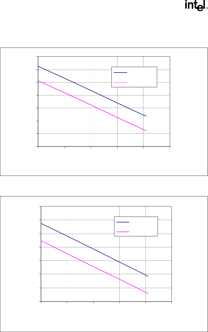
Figure 1-4. VRM 9.1 Regulation Requirement for 64-bit Intel
®
Xeon™ Processor MP
Cache (VID = 1.1275 V)
1.000
1.020
1.040
1.060
1.080
1.100
1.120
1.140
0 20406080100
Icc (A)
Vcc (V)
VvrmMAX
VvrmMIN
1.160
1.180
1.200
1.220
1.240
1.260
1.280
1.300
0 20406080100
Icc (A)
Vcc (V)
VvrmMAX
VvrmMIN