
Voltage Regulator Module (VRM) and Enterprise Voltage Regulator-Down (EVRD) 10.0 Design Guidelines

VRM and EVRD 10.0 Design Guidelines
R
12
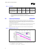
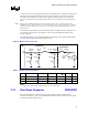
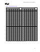
Table 1. Icc Guidelines
Icc(TDC) (A) Icc(Max) (A) Icc(Step) (A) Slew Rate (A/µs)
Intel® Xeon™ Processor with
800 MHz System Bus
85 100 70 560
Low Voltage Intel® Xeon™
processor with 800 MHz
system bus
56 60 38.5 308
NOTES:
1. See the Intel® Xeon™ Processor with 800 MHz System Bus Datasheet and Low Voltage Intel® Xeon™
processor with 800 MHz System Bus Datasheet for the latest specifications.
2. This table represents the expected operating limitations for VRM/EVRD 10.0. Future Intel® Xeon™
processors with 800 MHz system bus will require a later version of the VRM/EVRD to reach end-of-life
capabilities.
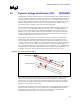
2.2 Load Line Definitions REQUIRED
The following load lines contain static and transient voltage data as well as maximum and
minimum voltage levels. Measurement of the load line is to be done at the remote sense point. It
is required that the remote sense point for the voltage regulator be connected to the processor
VCCSENSE and VSSSENSE pins.
The upper and lower load lines represent the allowable range of voltages that must be presented to
the processor. The voltage must never exceed these boundaries for proper operation of the
processor.
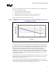
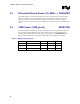
Figure 3 shows load line voltage offsets and current levels based on the VID specifications.
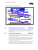
Figure 3. VRM/EVRD 10.0 Die Load Line
-0.180
-0.160
-0.140
-0.120
-0.100
-0.080
-0.060
-0.040
-0.020
0.000
020406080100
Icc (A)
Vcc (V) (Offset from VID)
Vmax
Vmin
The following equations for the load lines are valid for the range of load current from 0 to 100A.
• V
MAX
load line: Vcc = VID – (1.25 mΩ • Icc)
• V
MIN
load line: Vcc = VID – 0.040V – (1.25 mΩ • Icc)