
Voltage Regulator Module (VRM) and Enterprise Voltage Regulator-Down (EVRD) 10.0 Design Guidelines

VRM and EVRD 10.0 Design Guidelines
R
11
For the Low Voltage Intel® Xeon™ processor with 800MHz system bus, the VRM/EVRD will
be required to support the following:
• A continuous load current (Icc(TDC)) of 56A
• A maximum load current (Icc(Max)) of 60A
• A maximum load current step (Icc(Step)), within a 1 µs period, of 38.5A
• A maximum current slew rate at the pins of the processor of 308A/µs
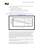
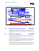
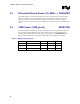
Figure 2 displays the load current requirements over time.
Figure 2 VRM/EVRD 10.0 Load Current vs. Time for Low Voltage Intel® Xeon™ Processor
with 800 MHz System Bus
54
55
56
57
58
59
60
61
62
0.01 0.1 1 10 100 1000
Time (s)
Load Current (A)
The continuous load current can also be referred to as the thermal design current (TDC). TDC is
the sustained (DC equivalent) current that the processor is capable of drawing indefinitely and
defines the current to use for the voltage regulator temperature assessment. At TDC, switching
FETs reach maximum temperature and may heat the baseboard layers and neighboring
components above valid thermal limits. Actual component and baseboard temperatures are
established by the envelope of the system operating conditions. This includes voltage regulator
layout, processor fan selection, ambient temperature, chassis configuration, etc. To avoid heat
related failures, baseboards should be validated for thermal compliance under the envelope of
system operating conditions.
The maximum load current represents the maximum peak current that the processor is capable of
drawing. It is the maximum current the VRM/EVRD must be electrically designed to support
without tripping any protection circuitry.
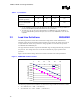
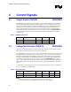
Table 1 lists the Icc guidelines for the flexible motherboard (FMB) frequency of the processor.
For designers who choose to design their VR thermal solution to the TDC, it is recommended that
voltage regulator thermal protection also be implemented (see Section 6.2).