
ITP700 Debug Port Design Guide


R
ITP700 Debug Port Design Guide 59
7 Intel
®
Pentium
®
4 Processor /
Mobile Intel
®
Pentium
®
4
Processor-M / Intel
®
Centrino
™
Mobile Technology System
Implementation Guidelines
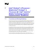
7.1 Termination and Routing Guidelines
The following specifications are for an ITP700 implementation that is terminated according to the
content in the Uniprocessor ITP Debug Port Implementation Guidelines chapter of this document
and adjusted specifically for the Intel
®
Pentium
®
4 processor in the 478-Pin Package, Intel
®
Pentium
®
4 processor with 512-KB L2 cache on 0.13 micron process, Intel
®
Pentium
®
4 processor
on 90 nm process, and systems based on Intel
®
Centrino™ mobile technology. If the system design
does not conform to the required terminations exactly, the additional drive specifications listed in
the Specifications chapter of this document can be used to interpolate specifications at the non-
standard operating ranges.
The Pentium 4 processor in the 478 Pin Package, Pentium 4 processor with 512-KB L2 cache on
0.13 micron process, Pentium 4 processor on 90 nm process, and systems based on Intel Centrino
mobile technology have identical ITP700 board level implementation requirements. The DC and
AC characteristics of the ITP signals, termination requirements and routing guidelines are the
identical. Therefore both processor families are discussed within this chapter. It is recommended
that systems based on Intel
®
Centrino
™
Mobile Technology implement the ITP700Flex debug
port. Implementation details can be found in Chapter 1 and Chapter 5.
All of the termination and routing guidelines defined in Chapter 1 must be adhered to for a
uniprocessor ITP700 debug port implementation with the following exceptions and clarifications: