
Intel Xeon Processor and Intel E7500/E7501Chipset Compatible Platform Design Guide


Baseboard Requirements
34 Intel
®
Xeon™ Processor and Intel
®
E7500/E7501 Chipset Compatible Platform Design Guide
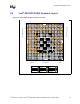
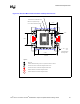
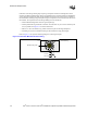
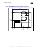
3.2 Processor Retention Mechanism Placement and
Keep-Outs
The Retention Mechanism (RM) for the Intel Xeon processor requires two keep-out zones: one for
the EMI ground pads, and another for a limited component height area under the RM. This is
specified in the Intel
®
Xeon™ Processor Datasheet. Figure 3-2 shows the relationship between the
RM mounting holes and pin one of the sockets; it also documents the ground pads and keep-outs.
Table 3-1. Board Requirements
Board Factor Recommendation
Material • Standard FR4 Tg 170 Epoxy.
Impedance
Requirements
•50 Ω impedance ± 10% Layers 2,4,5,7 (except lower left corner SCSI interface).
• SCSI interface 83 Ω single-ended, 122 Ω differential pair ± 10% (layers 1 and
8 lower-left corner using the reference stack-up).
Etch
• 5-mil trace width and space minimum inner/outer.
• SCSI interface: 6-mil separation within a pair, 20-mil space between adjacent pairs.
Finished Via Size
• Minimum via size is 0.014 mil, finished in a 0.026-mil land with 0.040-mil antipad.
• Approximately 15,000 plated through holes total.
Finish • Solder Mask On Bare Copper (SMOBC)
Soldermask Type • SM-840 minimum web 0.004 mils.
Fabrication • Edge Routed.
Component
Technology
• Through hole / SMT.
• QFP, BGA, front side.
• Discrete 0603, 0805 back side.