
Intel Xeon Processor and Intel E7500/E7501Chipset Compatible Platform Design Guide


Intel
®
Xeon™ Processor and Intel
®
E7500/E7501 Chipset Compatible Platform Design Guide 115
Intel
®
82870P2 (P64H2)
8.1.2 PCI/PCI-X Routing Requirements (No Hot-Plug Switch)
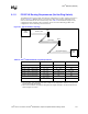
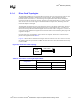
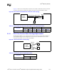
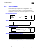
The P64H2 supports a large number of PCI/PCI-X configurations. The basic topology of the bus is
shown in Figure 8-1. Multiple slots are connected in a daisy chain topology with the device(s)
down on the motherboard at the end of the daisy chain. Table 8-4 documents the lengths for the
configurations Intel simulated. These topologies can also be used for Hot-Plug parallel mode
configurations where a Hot-Plug switch is not used.
NOTE:
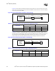
1. During simulation, slot to slot lengths were held constant for some configurations. Therefore, no range can be
given for these length requirements.
2. The 8.25 inches maximum only applies to the signals in the original 32-bit space. The 64-bit extension has a
maximum length of 7.0 inches.
Figure 8-1. Typical PCI/PCI-X Topology
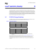
Table 8-4. Intel
®
P64H2 PCI/PCI-X Length Requirements
Configuration Intel
®
P64H2 to Slot Slot to Slot Slot to Device Down
33 MHz, 5 slots / 1 device down 2.0” – 7.0” 1.0” 3.0” – 6.0”
66 MHz, 4 slots / 0 devices down 6.0” – 8.0” 1.5” N/A
100 MHz, 2 slots / 0 devices down 5.0” – 8.0” 1.0” – 1.75” N/A
100 MHz, 2 slots / 1 device down 3.0” – 3.5” 0.75” 2.5” – 3.0”
100 MHz, 1 slot / 2 devices down 2.0” – 4.0” (device to device) 5.0” 2.0”
133 MHz, 1 slot / 0 devices down 1.0” – 8.25”
2
N/A N/A
133 MHz, 0 slots / 1 device down
1.25” – 10.0”
(P64H2 to device)
N/A N/A
Intel
®
P64H2
P64H2 to Slot
Slot to Slot
Slot 1
Slot 2
Slot to Device Down
Device
Down